Local computer network: design and network equipment. Building a local network Technical requirements for a LAN
Building a local network
In this article we will talk about the local network. It's no secret that local network installation at any facility is a vital necessity for business. Data exchange between computers, Internet access, IPtelephony, access to network printers and an enterprise server make the installation of a local network simply necessary for any company.
In small local networks, all computers are usually equal, i.e. users themselves choose which resources of their personal computer to make publicly available. Such networks are called peer-to-peer local networks. Thus, the user of a peer-to-peer local network chooses which folders and files to share and make available to other computers on the local network.
A more complex local network involves installing a server in it. If there are a large number of computers on the local network, in order to increase its performance, as well as to increase reliability when storing information on the local network, individual computers are allocated for storing data or application programs. A server machine differs from a regular computer in its higher performance, data storage array, and fault tolerance. The network in which the server is present is usually called a server-based local network.
In such a local network, the server can perform different tasks:
- Shared local network database
- connecting peripheral devices
- centralized local network management
- determining message transmission routes
Building a local network
Let's consider an example of building a peer-to-peer local network. Such a local network will consist of a modem, router, access point, hub and cable route. Installation of a local network begins with receiving technical specifications from the customer: network capacity, location of points, method of laying cable routes, room allocated for a server room or location for installing active equipment. Installation of a 100 megabit local network is usually carried out using a UTP network cable of category no lower than 5 AWG24 (4 pairs, cross-section of one core 0.5 mm). If the route for installing a local network runs near power cables or other sources of electromagnetic interference, it is better to use an FTP cable. The FTP and UTP network cable is distinguished by the presence of a screen with steel wire. Thus, FTP has better noise immunity characteristics, provided that at the end the cable is crimped with a metallized connector with the cable screen sealed under the connector and the computer has a ground loop. The total cable length of the line from the computer to the hub in theory should not exceed 100 m, but in practice, depending on the cable and the influence of electromagnetic components, it can reach up to 160 m, but from 100 Mbit/s about 4-7 Mbit/s remains. To build gigabit networks, category 6 cables, connectors and patch panels are used. In the server room or where the active equipment is installed, the network cable is crimped with RJ45 connectors or cross-connected to a patch panel and connected to the hub. On the other side there is a network socket to which the computer is connected. From the requirements for a personal computer: it must have a network adapter. A router is connected to the hub, which, as is often the case, is combined with a modem and an access point. Installation of a wireless access point can be done separately depending on the required coverage area. Setting up such a local network should not cause any difficulties. In a simple version, computers are on the same subnet and access the router to access the Internet. The access point also contacts the router to access the Internet. Thus, we have built a peer-to-peer network for a small company.
A larger local network will not do without installing a server. Installation of cabling begins in the same way with technical specifications as discussed above for a peer-to-peer local network. A technical specification must also be formed at a logical level: requirements for the server, software: database, ftp -server, Internet server, print server, security policy implementation. Typically, these requirements are presented to the administrator of the organization serving the local network or to the company that, along with the installation, configures the local network. In such a network, you can install a higher-level switch, with gigabit ports for connecting to, say, a gigabit server adapter. For example, in such a network, access to the Internet will already be provided through a server on which software is installed for providing access and monitoring the activities of personnel on the Internet. Each computer can have its own access rights determined by the security policy of the server in the domain. Each computer must enter a name and password issued by the network administrator to authorize in the domain.

In the end, let's summarize:
The first peer-to-peer network we reviewed is widely used in small offices and homes with up to 10 computers. Active equipment is inexpensive and easy to set up. Users of such a network can independently configure the security policy for their computer and share individual files and folders. Maintenance by a network administrator is not required.
Large local networks, which have high requirements for security, performance and other functionality, cannot do without server machines. Such a local network is difficult to set up, and the cost of active equipment increases significantly due to the server(s). The performance of such a network is much higher; the computer user's rights are limited by the general domain security policy. The server provides various services to user machines depending on access levels: access to the Internet, to network printers, to ftp -resources, mail, general database, etc. It is advisable to have an employee to maintain such a network. In a large distributed local network of an enterprise, there may be several servers, each of which will perform its own task: Internet server, ftp -server, print server, database server, server that is used for weak current: collecting reports from mini PBX, server for integrated security systems of video surveillance, access control, security and fire alarms.
Safe Kuban performs installation and maintenance of local wired and wireless systems in Krasnodar and the South of Russia
Send your good work in the knowledge base is simple. Use the form below
Students, graduate students, young scientists who use the knowledge base in their studies and work will be very grateful to you.
Posted on http://www.allbest.ru/
1. INTRODUCTION
The purpose of undergoing practical training in the specialty profile was to consolidate, deepen and systematize knowledge based on the activities of the company RadioZavod OJSC in the direction of “Management in Technical Systems”. During the internship period, the student’s theoretical and practical training plan was completed in full.
During the period from July 1 to July 29, I reviewed and studied the following: principles of building local computer networks; structure and operation of LAN; studying network protocols; basics of administration.
2. LOCAL COMPUTER NETWORKS
2.1 Local network topologies
LAN (English LAN - Local Area Network) refers to the joint connection of several separate computer workstations (workstations) to a single data transmission channel.
The topology of a computer network is understood as the configuration of a graph, the vertices of which correspond to computers on the network, and the edges correspond to physical connections between them. Computers connected to a network are often called stations or network nodes. Logical connections are data transmission routes between network nodes and are formed by appropriately configuring communication equipment.
The choice of electrical connection topology significantly affects many network characteristics. For example, the presence of redundant links increases network reliability and makes it possible to balance the load on individual links. The ease of connecting new nodes, inherent in some topologies, makes the network easily expandable. Economic considerations often lead to the selection of topologies characterized by the minimum total length of communication lines.
A fully connected topology (Figure 2.1, a) corresponds to a network in which each computer on the network is connected to all the others. Despite its logical simplicity, this option turns out to be cumbersome and ineffective. Indeed, each computer on the network must have a large number of communication ports, sufficient to communicate with each of the other computers on the network. A separate electrical communication line must be allocated for each pair of computers. Fully connected topologies are rarely used.
A cellular topology is obtained from a fully connected one by removing some possible connections (Figure 2.1, b). In a network with a mesh topology, only those computers between which intensive data exchange occurs are directly connected, and for data exchange between computers that are not directly connected, transit transmissions through intermediate nodes are used.
The common bus (Figure 2.1, c) is a very common topology for local networks. In this case, computers are connected to a single coaxial cable. The transmitted information can be distributed in both directions. The use of a common bus reduces wiring costs, unifies the connection of various modules, and provides the possibility of almost instantaneous broadcast access to all network stations. Thus, the main advantages of such a scheme are the low cost and ease of cable distribution throughout the premises. The most serious disadvantage of a common bus is its low reliability: any defect in the cable or connectors completely paralyzes the entire network. Another disadvantage of the shared bus is its low performance, since with this connection method only one computer at a time can transmit data to the network. Therefore, the communication channel bandwidth is always divided here between all network nodes.
Star topology (Figure 2.1, d). In this case, each computer is connected by a separate cable to a common device, called a hub, which is located at the center of the network. The function of a hub is to direct information transmitted by a computer to one or all other computers on the network. The main advantage of this topology is that any troubles with the cable affect only the computer to which this cable is connected, and only a malfunction of the hub can bring down the entire network. The disadvantages of a star topology include the higher cost of network equipment. In addition, the ability to increase the number of nodes in the network is limited by the number of hub ports. Sometimes it makes sense to build a network using several hubs, hierarchically connected to each other by star-type connections (Figure 2.1, e).
In networks with a ring configuration (Figure 2.1, e), data is transmitted along the ring from one computer to another, usually in one direction. If the computer recognizes the data as “its own,” then it copies it to its internal buffer. In a network with a ring topology, it is necessary to take special measures so that in the event of a failure or disconnection of any station, the communication channel between the remaining stations is not interrupted. The ring is a very convenient configuration for organizing feedback - the data, having made a full revolution, returns to the source node. Therefore, this node can control the process of delivering data to the recipient. Often this ring property is used to test network connectivity and find a node that is not working correctly.
Figure 2.1 Typical network topologies
2.2 Data transmission medium
A communication line (Figure 2.2) generally consists of a physical medium through which electrical information signals, data transmission equipment and intermediate equipment are transmitted.
Figure 2.2 Communication line composition
Physical environment data transmission can be a cable, that is, a set of wires, insulating and protective sheaths and connecting connectors, as well as the earth's atmosphere or outer space through which electromagnetic waves propagate. Depending on the data transmission medium, communication lines are divided into:
Wired (overhead) communication lines are wires without any insulating or shielding braiding, laid between poles and hanging in the air. Such communication lines traditionally carry telephone or telegraph signals, but in the absence of other options, these lines are also used to transmit computer data.
Cable lines are a rather complex structure. The cable consists of conductors enclosed in several layers of insulation: electrical, electromagnetic, mechanical. In addition, the cable can be equipped with connectors that allow you to quickly connect various equipment to it. There are three main types of cable used in computer networks: twisted pair copper cables, copper coaxial cables, and fiber optic cables.
Radio channels for terrestrial and satellite communications are formed using a radio wave transmitter and receiver. There are a large number of different types of radio channels, differing both in the frequency range used and in the channel range.
The main characteristics of communication lines include:
· amplitude-frequency response;
· bandwidth;
· attenuation;
· noise immunity;
· crosstalk at the near end of the line;
· throughput;
· reliability of data transmission;
· unit cost.
Factors affecting the physical performance of the network:
1) Serviceability of computers connected to the network.
2) Serviceability of network equipment (adapters, transceivers, connectors, etc.).
3) Integrity of the network cable.
4) Limitation of cable length associated with the attenuation of the signal propagating through it.
2.3 Types of local networks
There are several types of computer networks:
· Global networks,
· Regional networks,
· City networks.
Based on the speed of information transfer, computer networks are divided into:
· low-speed (up to 10 Mbit/s),
· medium-speed (up to 100 Mbit/s),
· high-speed (over 100 Mbit/s);
The term baud is widely used to define the speed of data transfer on a network. Baud is a unit of signal transmission rate measured by the number of discrete transitions or events per second. If each event represents one bit, baud is equivalent to bps.
From the point of view of organizing the interaction of computers, networks are divided into peer-to-peer (Peer-to-Peer Network) and with a dedicated server (Dedicated Server Network).
Peer-to-peer networks. All computers in a peer-to-peer network have equal rights. Any network user can access data stored on any computer. The advantage of peer-to-peer networks is that there is no need to copy all the files used by several users at once to the server. In principle, any network user has the ability to use all data stored on other computers on the network and devices connected to them. The main disadvantage of a peer-to-peer network is the significant increase in the time it takes to solve applied problems. This is due to the fact that each computer on the network processes all requests coming to it from other users.
In a network with a dedicated server, one of the computers performs the functions of storing data intended for use by all workstations, managing interaction between workstations, and a number of service functions. Interaction between workstations on a network is usually carried out through a server. The logical organization of such a network can be represented by a star topology. The role of the central device is performed by the server. Advantages of a network with a dedicated server: reliable information security system; high performance; no restrictions on the number of workstations; Ease of Management. Disadvantages of the network: high cost due to the allocation of one computer for the server; dependence of network speed and reliability on the server; less flexibility compared to a peer-to-peer network.
Modem connection. The most common and well-known method of connecting to the Internet in Russia is modem communication using a telephone line.
A modem is connected to the computer - a device for receiving and transmitting data, which is connected to a regular telephone line. When it is necessary to establish a connection, a modem is used to dial a telephone number, which is answered by another modem installed at the Internet provider. A connection is established between the modems and data is transferred.
The main advantage of modem communication is its prevalence and low price. If a high-quality telephone line is available, modem communication is also available - there is no need to organize a special channel. The initial cost of connecting to a modem provider is low. However, modem communication also has major disadvantages, a significant part of which is associated with the deplorable state of the bulk of Russian telephone lines. A well-known problem with modem communication is low speed. Theoretically, modern modems are capable of transmitting data at speeds of up to 56 Kbps from the provider to the user and up to 40 Kbps from the user to the provider.
TechnologyEthernet
Ethernet is the most widespread local network standard today. When people say Ethernet, they usually mean any of the variants of this technology. In a narrower sense, Ethernet is a network standard based on the experimental Ethernet Network.
Ethernet standards define wire connections and electrical signals at the physical layer, frame formats and media access control protocols at the data link layer of the OSI model.
Depending on the type of physical medium, the IEEE 802.3 standard has various modifications - l0Base-5, l0Base-2, l0Base-T, l0Base-FL, l0Base-FB.
Ethernet networks use a medium access method called carrier-sense-multiply-access with collision detection (CSMA/CD).
This method is used exclusively in networks with a logical common bus. All computers on such a network have direct access to a common bus, so it can be used to transfer data between any two network nodes. At the same time, all computers on the network have the opportunity to immediately (taking into account the delay in signal propagation through the physical medium) receive data that any of the computers has begun to transmit to the common bus.
All data transmitted over the network is placed in frames of a certain structure and provided with a unique address of the destination station. The frame is then transmitted over the cable. All stations connected to the cable can recognize the fact of frame transmission, and the station that recognizes its own address in the frame headers writes its contents to its internal buffer, processes the received data and sends a response frame along the cable. The source station's address is also included in the original frame, so the destination station knows who to send the response to.
With the described approach, it is possible that two stations simultaneously try to transmit a data frame over a common cable. To reduce the likelihood of this situation, immediately before sending a frame, the transmitting station analyzes the occurrence of electrical signals on it to detect whether a data frame from another station is already being transmitted along the cable. If a carrier-sense (CS) is recognized, then the station postpones transmitting its frame until the end of someone else's transmission, and only then tries to transmit it again.
To correctly handle a collision, all stations simultaneously monitor the signals appearing on the cable. If the transmitted and observed signals differ, then collision detection (CD) is detected.
Token Ring is a local area network (LAN) ring technology with “token access”.
Token Ring technology is a more complex technology than Ethernet. It has fault tolerance properties. The Token Ring network defines network operation control procedures that use feedback of a ring-shaped structure - the sent frame always returns to the sending station. In some cases, detected errors in the network operation are eliminated automatically, for example, a lost token can be restored.
In the Token Ring network, a ring is formed by sections of cable connecting neighboring stations. Thus, each station is connected to its predecessor and successor station and can only communicate directly with them. To provide stations with access to the physical environment, a frame of a special format and purpose - a token - circulates around the ring.
Having received the marker, the station analyzes it and, if it does not have data to transmit, ensures its progress to the next station. A station that has data to transmit, upon receiving the token, removes it from the ring, which gives it the right to access the physical medium and transmit its data. This station then sends a data frame of the established format into the ring bit by bit. The transmitted data always passes along the ring in one direction from one station to another. The frame is provided with a destination address and a source address.
All stations on the ring relay the frame bit by bit, like repeaters. If the frame passes through the destination station, then, having recognized its address, this station copies the frame to its internal buffer and inserts an acknowledgment sign into the frame. The station that issued the data frame to the ring, upon receiving it back with confirmation of receipt, removes this frame from the ring and transmits a new token to the network to enable other network stations to transmit data.
2.4 High-speed fiber optic networks
Because fiber optic cable uses light (photons) instead of electricity, almost all of the problems inherent in copper cable, such as electromagnetic interference, crosstalk (crosstalk) and the need for grounding, are completely eliminated. It also provides increased secrecy of transmitted data compared to copper, since it does not emit electromagnetic radiation, and it is almost impossible to connect to it without destroying the integrity.
The disadvantages of optical fiber are mainly related to its installation and operating costs, which are usually much higher than for copper data transmission media.
Today, fiber is positioned as a high-speed networking technology, and virtually all link-layer protocols in use use it in one form or another. Here are some of them:
Fast Ethernet (100BaseFX);
Gigabit Ethernet (1000BaseFX);
Fiber Distributed Data Interface (FDDI);
Asynchronous Transfer Mode;
This method provides the highest speeds to date, which provides a good reason for the development of data transmission technologies over optical fiber. Bandwidth can reach the order of Terabits (1000 gigabits) per second. When compared with other methods of information transmission, the order of magnitude Tbit/s is simply unattainable.
2.5 Wireless network technologies
Wireless technologies are a subclass of information technologies that serve to transmit information over a distance between two or more points, without requiring their connection by wires. Infrared radiation, radio waves, optical or laser radiation can be used to transmit information.
Currently, there are many wireless technologies, most often known to users by their marketing names, such as Wi-Fi, WiMAX, Bluetooth. Each technology has certain characteristics that determine its scope of application.
WiFi. Typically, a Wi-Fi network diagram contains at least one access point and at least one client. It is also possible to connect two clients in point-to-point mode, when the access point is not used, and the clients are connected via network adapters “directly”. The access point transmits its network identifier (SSID) using special signaling packets at a speed of 0.1 Mbit/s every 100 ms. Therefore, 0.1 Mbit/s is the lowest data transfer speed for Wi-Fi. Knowing the network's SSID, the client can determine whether a connection to a given access point is possible. When two access points with identical SSIDs are within range, the receiver can choose between them based on signal strength data.
WiMAX is a telecommunications technology designed to provide universal wireless communications over long distances to a wide range of devices.
In general, WiMAX networks consist of the following main parts: base and subscriber stations, as well as equipment connecting the base stations with each other, with the service provider and with the Internet.
To connect the base station to the subscriber station, a high-frequency radio wave range from 1.5 to 11 GHz is used. Under ideal conditions, data exchange rates can reach 70 Mbit/s without requiring line-of-sight between the base station and the receiver. Line-of-sight connections are established between base stations using the frequency range from 10 to 66 GHz, data exchange speeds can reach 140 Mbit/s. In this case, at least one base station is connected to the provider's network using classic wired connections.
Bluetooth is a low-power radio technology designed to replace existing cable connections between office and home appliances and a wide range of portable devices (mobile phones, digital cameras, record players, etc.).
The technology uses small, short-range transceivers, either directly built into the device or connected through a free port or PC card. Adapters operate within a radius of up to 10 m.
Devices using the Bluetooth standard operate in the 2.4 GHz ISM (Industrial, Scientific, Medical - industrial, scientific and medical band) band and are capable of transmitting data at speeds up to 720 Kbps. Such performance is achieved using a transmission power of 1 MW and using a frequency switching mechanism to prevent interference.
3. NETWORK PROTOCOLS
3.1 MAC addresses
A MAC address (Media Access Control) is a unique identifier assigned to each piece of computer network equipment.
On broadcast networks (such as Ethernet-based networks), the MAC address allows each node on the network to be uniquely identified and data can be delivered only to that node. Thus, MAC addresses form the basis of networks at the data link layer, which is used by higher-layer protocols. To convert MAC addresses to network layer addresses and vice versa, special protocols are used (for example, ARP and RARP in TCP/IP networks).
MAC address structure
· The first bit of the destination MAC address is called the I/G (broadcast) bit. In the source address it is called the Source Route Indicator.
The second bit determines how the address is assigned
· The three most significant bytes of the address are called the Burned In Address (BIA) or Organizationally Unique Identifier (OUI)
· The manufacturer himself is responsible for the uniqueness of the lower three bytes of the address.
Figure 3.1 MAC Address Structure
3.2 OSI model
Just because a protocol is an agreement adopted by two interacting entities, in this case two computers operating on a network, does not mean that it is necessarily standard. But in practice, when implementing networks, standard protocols are usually used. These may be proprietary, national or international standards.
In the early 80s, a number of international standardization organizations - ISO, ITU-T and some others - developed a model that played a significant role in the development of networks. This model is called the ISO/OSI model.
The Open System Interconnection (OSI) model defines the different layers of interconnection between systems in packet-switched networks, gives them standard names, and specifies what functions each layer should perform.
In the OSI model (Figure 3.2), communication means are divided into seven layers: application, presentation, session, transport, network, link and physical. Each layer deals with a specific aspect of network device interaction.
Figure 3.2 OSI Model
The physical layer receives data packets from the upper link layer and converts them into optical or electrical signals corresponding to 0 and 1 of the binary stream. These signals are sent through the transmission medium to the receiving node. The mechanical and electrical/optical properties of the transmission medium are determined at the physical layer and include: the type of cables and connectors, the pinout of the connectors, the signal coding scheme for the values 0 and 1.
Physical layer protocols: IRDA, USB, EIA RS-232, RS-485, Ethernet (including 10BASE-T, 10BASE2, 10BASE5, 100BASE-TX, 100BASE-FX, 100BASE-T, 1000BASE-T, 1000BASE-SX and others) , 802.11Wi-Fi, DSL, ISDN, IEEE 802.15, Firewire.
The data link layer ensures the transmission of data packets coming from upper-layer protocols to the destination node, whose address is also indicated by the upper-layer protocol. One of the tasks of the link layer is to check the availability of the transmission medium. Another task of the link layer is the implementation of error detection and correction mechanisms.
The IEEE 802.x specifications divide the link layer into two sublayers: logical link control (LLC) and media access control (MAC). The LLC provides network layer services, and the MAC sublayer regulates access to the shared physical medium.
Protocols: ATM, Fiber Distributed Data Interface (FDDI), IEEE 802.11 wireless LAN, Link Access Procedures, Point-to-Point Protocol (PPP), Serial Line Internet Protocol (SLIP) (obsolete), Unidirectional Link Detection (UDLD), x .25.
The network layer is designed to determine the path for data transmission. Responsible for translating logical addresses and names into physical ones, determining the shortest routes, switching and routing, and monitoring network problems.
Example: IP/IPv4/IPv6 (Internet Protocol), IPX (Internetwork Packet Exchange), X.25 (partially implemented at Layer 2), CLNP (Connectionless Network Protocol), IPsec (Internet Protocol Security) , ICMP (Internet Control Message Protocol), RIP (Routing Information Protocol), ARP (Address Resolution Protocol).
The transport layer is designed to deliver data without errors, loss or duplication in the sequence in which it was transmitted. It does not matter what data is transmitted, from where and where, that is, it provides the transmission mechanism itself. It divides data blocks into fragments (UDP datagram, TCP segment), the size of which depends on the protocol; short ones are combined into one, and long ones are split.
Example: ATP (AppleTalk Transaction Protocol), FCP (Fiber Channel Protocol), NBF (NetBIOS Frames protocol), NCP (NetWare Core Protocol), SPX (Sequenced Packet Exchange), TCP (Transmission Control Protocol), UDP (User Datagram Protocol) .
The session layer of the model is responsible for maintaining a communication session, allowing applications to interact with each other for a long time. The layer manages session creation/termination, information exchange, task synchronization, data transfer eligibility determination, and session maintenance during periods of application inactivity.
Example: ISO-SP (OSI Session Layer Protocol (X.225, ISO 8327)), L2F (Layer 2 Forwarding Protocol), NetBIOS (Network Basic Input Output System), PPTP (Point-to-Point Tunneling Protocol), RPC ( Remote Procedure Call Protocol), SMPP (Short Message Peer-to-Peer), ZIP (Zone Information Protocol), SDP (Sockets Direct Protocol).
The representative level deals with the form of presentation of information transmitted over the network, without changing its content. Presentation layer - coordinates the presentation (syntax) of data during the interaction of two application processes: converting data from an external format to an internal one. At this level, data encryption and decryption can be performed, thanks to which the secrecy of data exchange is ensured for all application services at once.
The application layer is really just a collection of various protocols that enable network users to access shared resources, such as files, printers, or hypertext Web pages, and to collaborate, such as through the email protocol.
Example: HTTP, POP3, SMTP, FTP, XMPP, OSCAR, Modbus, SIP, TELNET.
The IPX protocol is designed for the transmission of datagrams in connectionless systems, it provides communication between NetWare servers and end stations. IPX packets can be broadcast.
The SPX protocol is a serial packet exchange protocol. It is a connection-based transport layer protocol. Works on top of the IPX network protocol. It is assumed that a connection is established between the workstations before the message is sent. At the SPX protocol level, the reliability (reliability) of information transmission increases dramatically. If the packet is transmitted incorrectly, it is retransmitted.
The NetBEUI protocol, due to its primitiveness, requires the least resources and provides the highest speed, but due to a number of inherent disadvantages, such as the impossibility of routing and strong noise in a large network, NetBEUI can only be effectively used in small local networks (IBM developed the NetBEUI protocol for local networks containing about 20 - 200 workstations).
TCP is a connection-oriented protocol located at the transport layer of the TCP/IP stack, between the IP protocol and its own application. The IP protocol deals with sending datagrams over the network without guaranteeing delivery, integrity, the order of arrival of information and the readiness of the recipient to receive data; all these tasks are assigned to the TCP protocol.
SMTP is a network protocol designed for transmitting email over TCP/IP networks. Work with SMTP occurs directly on the recipient's server. Supports functions: connection establishment, authentication, data transfer. Currently, SMTP is the standard protocol for email and is used by all clients and servers.
POP3 (Post Office Protocol Version 3) is used by the email client to receive email messages from the server. Typically used in conjunction with the SMTP protocol. Mail messages are received by the mail server and stored there until the POP3 application is launched on the client workstation. This application establishes a connection to the server and retrieves messages from there.
IMAP is an application layer protocol for accessing email. Similar to POP3, it is used to work with incoming letters, but provides additional functions, in particular, the ability to search by keyword without saving mail in local memory.
SMB/CIFS is an application-level network protocol for remote access to files, printers and other network resources, as well as for inter-process communication.
HTTP -- "Hypertext Transfer Protocol", an application layer protocol for data transfer. HTTP is now widely used on the World Wide Web to retrieve information from websites.
HTTPS is an extension of the HTTP protocol that supports encryption. It provides protection against attacks based on network eavesdropping.
FTP is a protocol designed for transferring files over computer networks. FTP allows you to connect to FTP servers, view directory contents, and download files from or to a server. The FTP protocol is an application layer protocol and uses the TCP transport protocol to transfer data.
4. ROUTING BASICS
4.1 Network equipment
Network cards are controllers that are plugged into expansion slots on a computer's motherboard and are designed to transmit signals to the network and receive signals from the network.
Hubs are the central devices of a cable system or a star physical topology network, which, when receiving a packet on one of its ports, forwards it to all the others. The result is a network with a logical common bus structure.
Repeaters are network devices that amplifies and re-forms the shape of the incoming analog network signal over a distance of another segment. A repeater operates at an electrical level to connect two segments. Repeaters do not recognize network addresses and therefore cannot be used to reduce traffic.
Switches are software-controlled central devices of the cable system that reduce network traffic due to the fact that the incoming packet is analyzed to determine the address of its recipient and, accordingly, is transmitted only to him.
Routers are standard network devices that operate at the network level and allow you to forward and route packets from one network to another, as well as filter broadcast messages.
4.2 Routing
topology network communication routing
Routing is the process of determining the route for information in communication networks.
Routes can be specified administratively (static routes) or calculated using routing algorithms based on information about the topology and state of the network obtained using routing protocols (dynamic routes).
A routing table is a spreadsheet or database stored on a router that describes the mapping between destination addresses and the interfaces through which a data packet should be sent to the next router.
The routing table usually contains: the address of the destination network or node; destination network mask; gateway, indicating the address of the router on the network to which the packet must be sent to the specified destination address; metric -- a numeric indicator that specifies the route preference. The lower the number, the more preferred the route (intuitively represented as distance).
Static routing is a type of routing in which routes are specified explicitly when configuring the router. All routing occurs without the participation of any routing protocols.
Dynamic routing is when table entries are updated automatically using one or more routing protocols.
IP address is a unique network address of a node in a computer network built using the IP protocol. The address consists of two parts - the network number and the node number in the network
Automatic distribution. With this method, each computer is allocated an arbitrary free IP address from a range defined by the administrator for permanent use.
Dynamic distribution. This method is similar to automatic distribution, except that the address is issued to the computer not for permanent use, but for a certain period.
Figure 4.1 Routing in TCP/IP networks
DNS is a distributed computer system for obtaining information about domains. Most often used to obtain an IP address by host name (computer or device), obtain information about mail routing, serving hosts for protocols in a domain.
ARP is a low-level protocol used in computer networks, designed to determine the link layer address from a known network layer address.
A node that needs to map an IP address to a local address generates an ARP request, inserts it into a link-layer protocol frame, indicating a known IP address in it, and broadcasts the request. All hosts on the local network receive an ARP request and compare the IP address specified there with their own. If they match, the node generates an ARP response, in which it indicates its IP address and its local address and sends it already directed, since in the ARP request the sender indicates its local address.
Address translation is performed by searching the table. This table, called the ARP table, is stored in memory and contains rows for each host on the network. Two columns contain IP and Ethernet addresses. If you need to convert an IP address to an Ethernet address, the entry with the corresponding IP address is searched.
Figure 4.2. ARP table
The ARP table is necessary because IP addresses and Ethernet addresses are chosen independently, and there is no algorithm for converting one to the other. The IP address is selected by the network manager taking into account the machine’s position on the Internet. If a machine is moved to another part of the internet, its IP address must be changed. The Ethernet address is selected by the manufacturer of the network interface equipment from the address space allocated for it under the license. When a machine's network adapter card is replaced, its Ethernet address also changes.
5. CONCLUSION
During the period of practical training in the specialty profile, the following were considered:
1) principles of constructing a LAN;
2) factors affecting network performance;
3) OSI network model;
Posted on Allbest.ru
Similar documents
Basic typical topologies of computer networks, their study, analysis, evaluation. Conclusion about the operation of networks with different topologies (chain, fully connected, mesh, combined). Advantages and disadvantages of topologies that affect network performance.
thesis, added 03/02/2009
General principles of organizing local networks, their typology and construction technology. Development of a project for combining two computer networks, comparison of configurations. Selecting a media converter, radio relay equipment, justification and configuration of the router.
thesis, added 03/18/2015
Characteristics of the main network interconnection devices. Main functions of the repeater. Physical structuring of computer networks. Rules for the correct construction of Fast Ethernet network segments. Features of using 100Base-T equipment in local networks.
abstract, added 01/30/2012
Theoretical foundations of organizing local computer networks: definition of LAN, topology, data exchange protocols used for connecting workstations and computers; software. Network environment; identifying a computer using an IP address.
course work, added 05/15/2014
The composition of a local computer network, its main elements and their purpose. The role of cables in building local connections of computer networks, the advantages of their use. Types and configurations of cables, their design features and application.
thesis, added 06/08/2009
The purpose of the switch, its tasks, functions, technical characteristics. Advantages and disadvantages compared to a router. Fundamentals of technology for organizing cable network systems and the architecture of local computer networks. OSI reference model.
practice report, added 06/14/2010
Study of local networks. Features of various types of local network topologies: bus, star, ring. OSI reference model. The essence of the structural approach to the creation of structured information systems. Transfer of information on the network. Packet addressing.
abstract, added 12/17/2010
Development of an option for integrating local computer networks of MIET and the MIET campus, satisfying both parties. Analysis of the feasibility of implementing communication between the MIET LAN and the MIET Campus via a radio channel. Review of radio network equipment technologies.
thesis, added 09/10/2010
Classification of telecommunication networks. Channel diagrams based on the telephone network. Types of non-switched networks. The emergence of global networks. Problems of a distributed enterprise. The role and types of global networks. Option for combining local networks.
presentation, added 10/20/2014
Classification of networks and switching methods. Types of communications and operating modes of message transmission networks. Unification and standardization of protocols. Reference model for open systems interconnection. Features of data preparation. Interaction of information systems.
Why are local networks needed, and what are they? How to connect several computer devices to one Internet channel at once? What equipment is required to build a home network? You will receive answers to all these and other equally important questions in this material.
Introduction
Before you learn how to design and configure home local networks yourself, let’s immediately answer the most important question: “Why are they needed?”
The concept of a local network itself means the unification of several computers or computer devices into a single system for the exchange of information between them, as well as the sharing of their computing resources and peripheral equipment. Thus, local networks allow:
Exchange data (movies, music, programs, games, etc.) between network members. At the same time, to watch movies or listen to music, it is absolutely not necessary to record them on your hard drive. The speeds of modern networks allow this to be done directly from a remote computer or multimedia device.
Connect several devices simultaneously to the global Internet through one access channel. This is probably one of the most popular functions of local networks, because these days the list of equipment that can use a connection to the World Wide Web is very large. In addition to all kinds of computer equipment and mobile devices, TVs, DVD/Blu-Ray players, multimedia players and even all kinds of household appliances, from refrigerators to coffee makers, have now become full participants in the network.
Share computer peripherals , such as printers, MFPs, scanners and network attached storage (NAS).
Share the computing power of computers of network participants. When working with programs that require complex calculations, such as 3D visualization, to increase productivity and speed up data processing, you can use the free resources of other computers on the network. Thus, having several weak machines connected to a local network, you can use their combined performance to perform resource-intensive tasks.
As you can see, creating a local network even within one apartment can bring a lot of benefits. Moreover, having several devices at home that require an Internet connection has long been not uncommon, and combining them into a common network is an urgent task for most users.
Basic principles of building a local network
Most often, local networks use two main types of data transfer between computers - via wire, such networks are called cable and use Ethernet technology, and also using a radio signal over wireless networks built on the basis of the IEEE 802.11 standard, which is better known to users under the name Wi -Fi.
Today, wired networks still provide the highest bandwidth, allowing users to exchange information at speeds of up to 100 Mbps (12 Mbps) or up to 1 Gbps (128 Mbps) depending on the equipment used (Fast Ethernet or Gigabit Ethernet). And although modern wireless technologies, purely theoretically, can also provide data transfer up to 1.3 Gbit/s (Wi-Fi 802.11ac standard), in practice this figure looks much more modest and in most cases does not exceed 150 - 300 Mbit/s. The reason for this is the high cost of high-speed Wi-Fi equipment and the low level of its use in current mobile devices.
As a rule, all modern home networks are arranged according to the same principle: user computers (workstations) equipped with network adapters are connected to each other through special switching devices, which can be: routers (routers), switches (hubs or switches), points access or modems. We will talk in more detail about their differences and purposes below, but for now just know that without these electronic boxes, it will not be possible to combine several computers into one system at once. The maximum that can be achieved is to create a mini-network of two PCs by connecting them to each other.
At the very beginning, you need to determine the basic requirements for your future network and its scale. After all, the choice of the necessary equipment will directly depend on the number of devices, their physical placement and possible connection methods. Most often, a home local network is combined and can include several types of switching devices. For example, desktop computers can be connected to the network using wires, and various mobile devices (laptops, tablets, smartphones) can be connected via Wi-Fi.
For example, consider the diagram of one of the possible options for a home local network. It will involve electronic devices designed for various purposes and tasks, as well as using different types of connections.

As can be seen from the figure, several desktop computers, laptops, smartphones, set-top boxes (IPTV), tablets and media players and other devices can be combined into a single network. Now let's figure out what equipment you will need to build your own network.
LAN card
A network card is a device that allows computers to communicate with each other and exchange data on a network. All network adapters can be divided into two large groups by type - wired and wireless. Wired network cards allow you to connect electronic devices to a network using Ethernet technology using a cable, while wireless network adapters use Wi-Fi radio technology.

As a rule, all modern desktop computers are already equipped with Ethernet network cards built into the motherboard, and all mobile devices (smartphones, tablets) are equipped with Wi-Fi network adapters. At the same time, laptops and ultrabooks are mostly equipped with both network interfaces at once.

Despite the fact that in the vast majority of cases, computer devices have built-in network interfaces, sometimes it becomes necessary to purchase additional cards, for example, to equip the system unit with a Wi-Fi wireless communication module.

Based on their design implementation, individual network cards are divided into two groups - internal and external. Internal cards are designed for installation in desktop computers using interfaces and their corresponding PCI and PCIe slots. External cards are connected via USB connectors or legacy PCMCIA (laptops only).
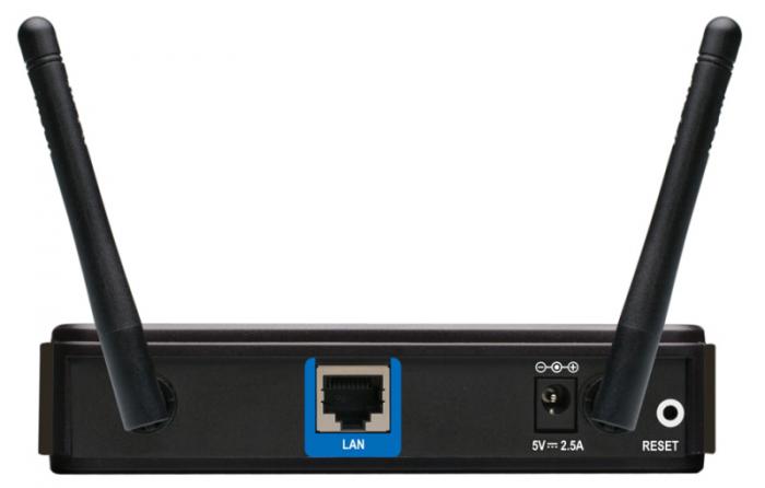
Router (Router)
The main and most important component of a home local network is a router or router - a special box that allows you to combine several electronic devices into a single network and connect them to the Internet through one single channel provided to you by your provider.
.jpg)
A router is a multifunctional device or even a minicomputer with its own built-in operating system, which has at least two network interfaces. The first one is LAN (Local Area Network ) or LAN (Local Area Network) is used to create an internal (home) network, which consists of your computer devices. The second - WAN (Wide Area Network) or WAN (Wide Area Network) is used to connect a local network (LAN) to other networks and the World Wide Web - the Internet.
The main purpose of devices of this type is to determine the routes of data packets that the user sends to or requests from other, larger networks. It is with the help of routers that huge networks are divided into many logical segments (subnets), one of which is the home local network. Thus, at home, the main function of a router can be called organizing the transfer of information from a local network to a global one, and vice versa.
Another important job of a router is to limit access to your home network from the World Wide Web. Surely you are unlikely to be happy if anyone can connect to your computers and take or delete from them whatever they want. To prevent this from happening, the data flow intended for devices belonging to a specific subnet must not go beyond its boundaries. Therefore, from the general internal traffic generated by local network participants, the router selects and sends to the global network only that information that is intended for other external subnets. This ensures the security of internal data and saves overall network bandwidth.
The main mechanism that allows the router to limit or prevent access from the public network (outside) to devices on your local network is called NAT (Network Address Translation). It also provides all users of your home network with access to the Internet by converting multiple internal device addresses into one public external address that is provided to you by your Internet service provider. All this makes it possible for computers on a home network to easily exchange information with each other and receive it from other networks. At the same time, the data stored in them remains inaccessible to external users, although access to it can be provided at any time at your request.
In general, routers can be divided into two large groups - wired and wireless. Already from the names it is clear that all devices are connected to the first ones only using cables, and to the second ones, both with the help of wires and without them using Wi-Fi technology. Therefore, at home, wireless routers are most often used to provide Internet access and network computer equipment using various communication technologies.
To connect computer devices using cables, the router has special sockets called ports. In most cases, the router has four LAN ports for connecting your devices and one WAN port for connecting your ISP cable.

In order not to overload the article with redundant information, we will not consider in detail the main technical characteristics of routers in this chapter; I will talk about them in a separate article, on choosing a router.
In many cases, a router may be the only component needed to build your own local network, since there is simply no need for the rest. As we have already said, even the simplest router allows you to connect up to four computer devices using wires. Well, the number of equipment that receives simultaneous access to the network using Wi-Fi technology can be in the tens, or even hundreds.
If, at some point, the number of LAN ports on the router is no longer enough, then to expand the cable network, you can connect one or more switches to the router (discussed below), which act as splitters.
Modem
In modern computer networks, a modem is a device that provides access to the Internet or access to other networks through regular wired telephone lines (xDSL class) or using wireless mobile technologies (3G class).

Conventionally, modems can be divided into two groups. The first includes those that connect to a computer via a USB interface and provide network access to only one specific PC, to which the modem is directly connected. In the second group, the already familiar LAN and/or Wi-Fi interfaces are used to connect to a computer. Their presence indicates that the modem has a built-in router. Such devices are often called combined, and they should be used to build a local network.

When choosing DSL equipment, users may encounter certain difficulties caused by confusion in its names. The fact is that often in the assortment of computer stores, two very similar classes of devices are located side by side: modems with built-in routers and routers with built-in modems. What is the difference between them?

These two groups of devices practically do not have any key differences. Manufacturers themselves position a router with a built-in modem as a more advanced option, equipped with a large number of additional functions and improved performance. But if you are only interested in basic capabilities, for example, such as connecting all computers on your home network to the Internet, then there is not much difference between modem-routers and routers where a DSL modem is used as an external network interface.
So, to summarize, a modern modem with which you can build a local network is, in fact, a router with an xDSL or 3G modem as an external network interface.
A switch or switch is used to connect various nodes of a computer network and exchange data between them via cables. The role of these nodes can be either individual devices, for example a desktop PC, or entire groups of devices united into an independent network segment. Unlike a router, a switch has only one network interface - LAN and is used at home as an auxiliary device primarily for scaling local networks.

To connect computers using wires, like routers, switches also have special socket ports. In models aimed at home use, their number is usually five or eight. If at some point the number of ports on the switch is no longer enough to connect all devices, you can connect another switch to it. Thus, you can expand your home network as much as you like.
Switches are divided into two groups: managed and unmanaged. The first, as the name suggests, can be controlled from the network using special software. Although they have advanced functionality, they are expensive and not used at home. Unmanaged switches distribute traffic and regulate the speed of data exchange between all network clients automatically. These devices are ideal solutions for building small and medium-sized local networks, where the number of participants in the exchange of information is small.
Depending on the model, switches can provide a maximum data transfer speed of either 100 Mbit/s (Fast Ethernet) or 1000 Mbit/s (Gigabit Ethernet). Gigabit switches are best used for building home networks where you plan to frequently transfer large files between local devices.
Wireless access point
To provide wireless access to the Internet or local network resources, in addition to a wireless router, you can use another device called a wireless access point. Unlike a router, this station does not have an external WAN network interface and is equipped in most cases with only one LAN port for connecting to a router or switch. Thus, you will need an access point if your local network uses a regular router or modem without Wi-Fi support.

The use of additional access points in a network with a wireless router may be justified in cases where a large Wi-Fi coverage area is required. For example, the signal strength of a wireless router alone may not be enough to completely cover the entire area in a large office or multi-story country house.
Access points can also be used to organize wireless bridges, allowing you to connect individual devices, network segments or entire networks with each other using a radio signal in places where laying cables is undesirable or difficult.
Network cable, connectors, sockets
Despite the rapid development of wireless technologies, many local networks are still built using wires. Such systems have high reliability, excellent throughput and minimize the possibility of unauthorized connection to your network from the outside.
To create a wired local network in home and office environments, Ethernet technology is used, where the signal is transmitted over the so-called “twisted pair” (TP-Twisted Pair) - a cable consisting of four copper pairs of wires twisted together (to reduce interference).

When building computer networks, predominantly unshielded cable of the CAT5 category is used, and more often its improved version CAT5e. Cables of this category allow you to transmit a signal at a speed of 100 Mbit/s when using only two pairs (half) of wires, and 1000 Mbit/s when using all four pairs.
To connect to devices (routers, switches, network cards, and so on), 8-pin modular connectors, commonly called RJ-45 (although their correct name is 8P8C), are used at the ends of the twisted pair cable.

Depending on your desire, you can either buy ready-made (with crimped connectors) network cables of a certain length, called “patch cords”, at any computer store, or purchase twisted pair cables and connectors separately, and then make your own cables of the required size in the right quantity. You will learn how this is done in a separate material.
Using cables to connect computers into a network, of course, you can connect them directly from switches or routers to the connectors on the PC’s network cards, but there is another option - using network sockets. In this case, one end of the cable is connected to the switch port, and the other to the internal contacts of the socket, into the external connector of which you can subsequently connect computer or network devices.

Network sockets can be either built into the wall or mounted externally. Using sockets instead of protruding cable ends will give a more aesthetically pleasing look to your workspace. It is also convenient to use sockets as reference points for various network segments. For example, you can install a switch or router in the hallway of an apartment, and then thoroughly route cables from it to sockets located in all the necessary rooms. Thus, you will receive several points located in different parts of the apartment, to which you can at any time connect not only computers, but also any network devices, for example, additional switches to expand your home or office network.
Another little thing that you may need when building a cable network is an extension cord that can be used to connect two twisted pairs with already crimped RJ-45 connectors.

In addition to their intended purpose, extension cords are convenient to use in cases where the end of the cable ends not with one connector, but with two. This option is possible when building networks with a capacity of 100 Mbit/s, where it is enough to use only two pairs of wires to transmit a signal.
You can also use a network splitter to connect two computers to one cable at once without using a switch. But again, it is worth remembering that in this case the maximum data exchange speed will be limited to 100 Mbit/s.

For more information about crimping twisted pair cables, connecting sockets and the characteristics of network cables, read the special material.
Now that we've become familiar with the basic components of a local area network, it's time to talk about topology. In simple terms, a network topology is a diagram that describes the locations and methods of connecting network devices.
There are three main types of network topologies: Bus, Ring and Star. With a bus topology, all computers on the network are connected to one common cable. To unite PCs into a single network using the “Ring” topology, they are connected in series to each other, with the last computer connecting to the first. In a star topology, each device is connected to the network through a special hub using a separate cable.

Probably, the attentive reader has already guessed that to build a home or small office network, the “Star” topology is predominantly used, where routers and switches are used as hub devices.
Creating a network using the Star topology does not require deep technical knowledge and large financial investments. For example, using a switch that costs 250 rubles, you can connect 5 computers into a network in a few minutes, and using a router for a couple of thousand rubles, you can even build a home network, providing several dozen devices with access to the Internet and local resources.
Another undoubted advantage of this topology is good expandability and ease of upgrading. Thus, network branching and scaling is achieved by simply adding additional hubs with the necessary functionality. You can also change the physical location of network devices or swap them at any time in order to achieve more practical use of the equipment and reduce the number and length of connecting wires.
Despite the fact that the Star topology allows you to quickly change the network structure, the location of the router, switches and other necessary elements must be thought out in advance, in accordance with the layout of the room, the number of devices being connected and how they are connected to the network. This will minimize the risks associated with purchasing unsuitable or redundant equipment and optimize the amount of your financial costs.
Conclusion
In this material, we examined the general principles of building local networks, the main equipment that is used and its purpose. Now you know that the main element of almost any home network is a router, which allows you to network many devices using both wired (Ethernet) and wireless (Wi-Fi) technologies, while providing them all with an Internet connection through one single channel.
Switches, which are essentially splitters, are used as auxiliary equipment for expanding connection points to a local network using cables. To organize wireless connections, access points are used, which allow, using Wi-Fi technology, not only to connect all kinds of devices wirelessly to the network, but also to connect entire segments of the local network together in a “bridge” mode.
To understand exactly how much and what kind of equipment you will need to purchase to create a future home network, be sure to first draw up its topology. Draw a diagram of the location of all devices participating in the network that will require a cable connection. Depending on this, select the optimal location for the router and, if necessary, additional switches. There are no uniform rules here, since the physical location of the router and switches depends on many factors: the number and type of devices, as well as the tasks that will be assigned to them; layout and size of the room; requirements for the aesthetic appearance of switching nodes; possibilities for laying cables and others.
So, as soon as you have a detailed plan for your future network, you can begin to select and purchase the necessary equipment, install it and configure it. But we will talk about these topics in our next materials.
Federal Agency for Education
OMSK INSTITUTE
RUSSIAN STATE TRADE AND ECONOMICS UNIVERSITY
Department of Mathematics and Informatics
Test
In the course "Informatics"
On the topic: “Basic principles of construction
local area networks"
Option No. 25
Introduction………………………………………………………………………………………...2
1. The concept of LAN……………………………………………………………………..3
2. Basic OSI model (OpenSystemInterconnection)…………………………….5
3. LAN architecture………………………………………………………………………………...8
3.1. Types of networks…………………………………………………………………………………...8
3.2. Computer network topologies………………………………………….11
3.3. Network devices and communications……………………………15
3.3.1.Types of cables used……………………………………........15
3.3.2.Network card……………………………………………………….16
3.3.3.Splitter (HUB)……………………………………………………………..17
3.3.4.Repeater………………………………………………………......17
3.4. Types of network construction by methods of information transmission……………..18
4. Rules for installing the cable part of the LAN……………………………………19
References…………………………………………………………………………………26
Appendix………………………………………………………………………………………27
Today there are more than 130 million computers in the world and more than 80% of them are connected into various information and computer networks, from small local networks in offices to global networks such as the Internet. The worldwide trend towards connecting computers into networks is due to a number of important reasons, such as accelerating the transmission of information messages, the ability to quickly exchange information between users, receiving and transmitting messages (faxes, E-Mail letters, etc.) without leaving the workplace, the ability to instantly receive any information from anywhere in the world, as well as the exchange of information between computers of different manufacturers running different software.
Such huge potential opportunities that a computer network carries and the new potential rise that the information complex experiences at the same time, as well as the significant acceleration of the production process, do not give us the right not to accept this for development and not to apply it in practice.
Therefore, it is necessary to develop a fundamental solution to the issue of organizing an information and computer network on the basis of an existing computer park and software package that meets modern scientific and technical requirements, taking into account growing needs and the possibility of further gradual development of the network in connection with the emergence of new technical and software solutions.
1. The concept of LAN.
What is a local area network (LAN)? A LAN is understood as the joint connection of several separate computer workstations (workstations) to a single data transmission channel. Thanks to computer networks, we have the opportunity to simultaneously use programs and databases by several users.
The concept of local area network - LAN (eng. LAN - Lokal Area Network) refers to geographically limited (territorially or production) hardware and software implementations in which several computer systems are connected to each other using appropriate communications means. Thanks to this connection, the user can interact with other workstations connected to this LAN.
In production practice, LANs play a very important role. Through a LAN, the system combines personal computers located at many remote workplaces, which share equipment, software and information. Employees' workplaces are no longer isolated and are combined into a single system. Let's consider the benefits obtained by networking personal computers in the form of an intra-industrial computer network.
Resource sharing.
Resource sharing allows for efficient use of resources, such as managing peripherals such as laser printers from all connected workstations.
Data separation.
Data sharing provides the ability to access and manage databases from peripheral workstations that require information.
Software separation.
Software separation provides the opportunity to simultaneously use centralized, previously installed software.
Processor resource sharing.
By sharing processor resources, it is possible to use computing power to process data by other systems on the network. The opportunity provided is that the available resources are not “attacked” instantly, but only through a special processor available to each workstation.
Multiplayer mode .
The multi-user properties of the system facilitate the simultaneous use of centralized application software previously installed and managed, for example, if a user of the system is working on another task, the current work in progress is relegated to the background.
All LANs operate in the same standard adopted for computer networks - the Open Systems Interconnection (OSI) standard - open systems interaction.
Star topology.
The concept of a star network topology comes from the field of mainframe computers, in which the head machine receives and processes all data from peripheral devices as the active processing node. This principle is used in data communication systems, such as RELCOM e-mail. All information between two peripheral workstations passes through the central node of the computer network.
Fig.1 Star topology
Network throughput is determined by the computing power of the node and is guaranteed for each workstation. There are no data collisions.
Cabling is quite simple as each workstation is connected to a node. Cabling costs are high, especially when the central node is not geographically located in the center of the topology.
When expanding computer networks, previously made cable connections cannot be used: a separate cable must be laid from the center of the network to the new workplace.
The star topology is the fastest of all computer network topologies because data transfer between workstations passes through a central node (if its performance is good) over separate lines used only by these workstations. The frequency of requests to transfer information from one station to another is low compared to that achieved in other topologies.
The performance of a computer network primarily depends on the power of the central file server. It can be a bottleneck in the computer network. If the central node fails, the entire network is disrupted.
The central control node - the file server can implement the optimal protection mechanism against unauthorized access to information. The entire computer network can be controlled from its center.
Ring topology.
With a ring network topology, workstations are connected to one another in a circle, i.e. workstation 1 with workstation 2, workstation 3
Fig.2 Ring topology
with workstation 4, etc. The last workstation is connected to the first. The communication link is closed in a ring.
Laying cables from one workstation to another can be quite complex and expensive, especially if the workstations are geographically located far from the ring (for example, in a line).
Messages circulate regularly in circles. The workstation sends information to a specific destination address, having previously received a request from the ring. Message forwarding is very efficient since most messages can be sent “on the road” over the cable system one after another. It is very easy to make a ring request to all stations. The duration of information transfer increases in proportion to the number of workstations included in the computer network.
The main problem with a ring topology is that each workstation must actively participate in the transfer of information, and if at least one of them fails, the entire network is paralyzed. Faults in cable connections are easily localized.
Connecting a new workstation requires a short-term shutdown of the network, since the ring must be open during installation. There is no limit on the length of a computer network, since it is ultimately determined solely by the distance between two workstations.
With a bus topology, the information transmission medium is represented in the form of a communication path accessible to all workstations, to which they all must be connected. All workstations can communicate directly with any workstation on the network.
Fig.3 Bus topology
Workstations can be connected to or disconnected from it at any time, without interrupting the operation of the entire computer network. The functioning of a computer network does not depend on the state of an individual workstation.
In a standard situation, an Ethernet bus network often uses a thin cable or a Cheapernet cable with a T-connector. Shutting down and especially connecting to such a network requires a bus break, which disrupts the circulating flow of information and causes the system to freeze.
Tree structure of LAN.
Along with the well-known topologies of computer networks: ring, star and bus, a combined structure, for example a tree structure, is also used in practice. It is formed mainly in the form of combinations of the above-mentioned computer network topologies. The base of a computer network tree is located at the point (root) at which communication lines of information (tree branches) are collected.
Computer networks with a tree structure are used where direct application of basic network structures in their pure form is not possible.
Fig.4 Tree structure
3 .3. Network devices and communications.
The most commonly used means of communication are twisted pair, coaxial cable, and fiber optic lines. When choosing a cable type, take into account the following indicators:
· cost of installation and maintenance,
· information transfer speed,
· restrictions on the distance of information transmission without additional amplifiers-repeaters (repeaters),
· security of data transmission.
The main problem is to simultaneously ensure these indicators, for example, the highest data transfer rate is limited by the maximum possible data transmission distance, which still ensures the required level of data protection. Easy scalability and ease of expansion of the cable system affect its cost.
3.3.1. Types of cables used.
Twisted pair.
The cheapest cable connection is a twisted two-wire connection, often called a twisted pair. It allows you to transmit information at speeds of up to 10 Mbit/s, is easily expandable, but is not protected from interference. The cable length cannot exceed 1000 m at a transmission speed of 1 Mbit/s. The advantages are low price and ease of installation. To increase the noise immunity of information, shielded twisted pair cable is often used, i.e. twisted pair, placed in a shielding sheath, similar to the shield of a coaxial cable. This increases the cost of twisted pair and brings its price closer to the price of coaxial cable.
Ethernet cable.
The Ethernet cable is also a 50 ohm coaxial cable. It is also called thick Ethernet (thick), yellow cable (yellow cable) or 10BaseT5. It uses a 15-pin standard connection. Due to its immunity to noise, it is an expensive alternative to conventional coaxial cables. The maximum available distance without a repeater does not exceed 500 m, and the total distance of the Ethernet network is about 3000 m. The Ethernet cable, due to its backbone topology, uses only one load resistor at the end.
Cheapernet cable.
Cheaper than an Ethernet cable is a Cheapernet cable connection or, as it is often called, thin Ethernet or 10BaseT2. It is also a 50 ohm coaxial cable with an information transfer rate of ten million bits per second.
When connecting Chearenet cable segments, repeaters are also required. Computer networks with Cheapernet cable have a low cost and minimal expansion costs. Network cards are connected using widely used small-sized bayonet connectors (CP-50). No additional shielding is required. The cable is connected to the PC using T-connectors.
The distance between two workstations without repeaters can be a maximum of 300 m, and the total distance for a network on a Cheapernet cable is about 1000 m. The Cheapernet transceiver is located on the network board and both for galvanic isolation between adapters and for amplifying the external signal
Fiber optic lines.
The most expensive are optical conductors, also called fiberglass cable. The speed of information dissemination through them reaches several billion bits per second. The permissible distance is more than 50 km. There is virtually no external interference. This is currently the most expensive LAN connection. They are used where electromagnetic interference fields occur or information transmission over very long distances is required without the use of repeaters. They have anti-frizz properties, since the branching technique in fiber optic cables is very complex. The optical conductors are combined into a JIBC using a star connection.
Network adapter cards act as the physical interface, or connection, between the computer and the network cable. The cards are inserted into special sockets (expansion slots) of all computers and servers. To provide a physical connection between the computer and the network, a network cable is connected to the corresponding connector, or port, of the board (after its installation). Purpose of the network adapter card:
Preparing data coming from a computer for transmission via a network cable;
Transferring data to another computer;
Control the flow of data between the computer and the cable system;
The network adapter board takes data from the network cable and translates it into a form that the computer's central processor can understand.
The network adapter card consists of hardware and firmware stored in ROM (read-only memory). These programs implement the functions of the logical communication control sublayers and access control to the OSI model link layer environment.
The splitter serves as the central node in networks with a star topology.
When transmitted over a network cable, the electrical signal gradually weakens (attenuates). And, it is distorted to such an extent that the computer ceases to perceive it. To prevent signal distortion, a repeater is used, which amplifies (restores) the weakened signal and transmits it further along the cable. Repeaters are used in networks with a “bus” topology.
3.4. Types of network construction based on information transmission methods.
Local Token Ring Network.
This standard was developed by IBM. The transmission medium used is unshielded or shielded twisted pair (UPT or SPT) or optical fiber. Data transfer speed 4 Mbit/s or 16 Mbit/s. The Token Ring method is used as a method for controlling access of stations to the transmission medium. The main provisions of this method:
Devices are connected to the network using a ring topology;
All devices connected to the network can transmit data only after receiving permission to transmit (token);
At any given time, only one station in the network has this right.
IBM Token Ring uses three main types of packets:
Control/data package (Data/Command Frame);
Token;
Reset package (Abort).
Control/Data Package. Using such a packet, data or network control commands are transmitted.
Marker. A station can start transmitting data only after receiving such a packet. There can be only one token in one ring and, accordingly, only one station with the right to transmit data.
Reset Pack. Sending such a packet signals the termination of all transmissions.
You can connect computers in a network using a star or ring topology.
Ethernet local network.
The Ethernet specification was proposed by Xerox Corporation in the late seventies. Later, Digital Equipment Corporation (DEC) and Intel Corporation joined this project. In 1982, the Ethernet specification version 2.0 was published. Based on Ethernet, the IEEE 802.3 standard was developed by the IEEE Institute. The differences between them are minor.
Basic operating principles.
At the logical level, Ethernet uses a bus topology:
All devices connected to the network have equal rights, i.e. any station can start transmitting at any time (if the transmitting medium is free);
Data transmitted by one station is available to all stations in the network.
10BaseT
In 1990, IEEE released the 802.3 specification for twisted-pair Ethernet networks. 10 BaseT (10 – transmission speed 10 Mbit/s, Base – narrowband, T – twisted pair) is an Ethernet network that usually uses unshielded twisted pair (UTP) to connect computers. Most networks of this type are built in the form of a star, but the signal transmission system is a bus, like other Ethernet configurations. Typically, a 10BaseT network splitter acts as a multiport repeater. Each computer connects to the other end of the cable connected to the splitter and uses two pairs of wires: one for receiving and one for transmitting.
The maximum length of a 10BaseT segment is 100 m. The minimum cable length is 2.5 m. A 10BaseT LAN can serve up to 1024 computers.
To build a 10BaseT network use:
RJ – 45 connectors at the ends of the cable.
The distance from the workstation to the splitter is no more than 100 m.
10Base2
According to the IEEE 802.3 specification, this topology is called 10Base2 (10 - 10 Mbps transmission rate, Base - narrowband transmission, 2 - transmission over a distance of approximately twice 100 m (actual distance 185 m).
A network of this type is focused on a thin coaxial cable, or thin Ethernet, with a maximum segment length of 185 m. The minimum cable length is 0.5 m. In addition, there is a limit on the maximum number of computers that can be connected on a 185-meter cable segment - 30 things.
Thin Ethernet cable components:
BNC barrel – connectors (connectors);
BNC T – connectors;
BNC - terminators.
Thin Ethernet networks typically have a bus topology. IEEE standards for thin Ethernet do not require the use of a transceiver cable between the T connector and the computer. Instead, the T-connector is placed directly on the network adapter board.
BNC barrel connector, connecting cable segments, allows you to increase its total length. However, their use should be kept to a minimum as they degrade signal quality.
Thin Ethernet networking is a cost-effective way to implement networks for small offices and workgroups. The cable used in this type of network is relatively inexpensive, easy to install, and easy to configure. A thin Ethernet network can support up to 30 nodes (computers and printers) per segment.
A thin Ethernet network can consist of a maximum of five cable segments connected by four repeaters, but only three segments can be connected to workstations. Thus, two segments remain reserved for repeaters, they are called inter-repeater links. This configuration is called the 5 – 4 – 3 rule.
10Base5.
According to the IEEE specification, this topology is called 10Base5 (10 - 10 Mbit/s transmission rate, Base - narrowband transmission, 5 - 500 meter segments (5 times 100 meters)). There is another name for it - standard Ethrnet.
Networks on thick coaxial cable (thick Ethrnet) usually use a “bus” topology. Thick Ethrnet can support up to 100 nodes (workstations, repeaters, etc.) per backbone segment. The trunk, or trunk segment, is the main cable to which transceivers with workstations and repeaters connected to them are connected. A thick Ethernet segment can be 500 meters long for a total network length of 2500 meters. The distances and tolerances for thick Ethernet are greater than for thin Ethernet.
Cable system components:
Transceivers. Transceivers, providing communication between the computer and the main LAN cable, are combined with a “vampire tooth” connected to the cable.
Transceiver cables. The transceiver cable (drop cable) connects the cable to the network adapter board.
DIX – connector, or AUI – connector. This connector is located on the transceiver cable.
Barrel – connectors and terminators.
A thick Ethernet network can consist of a maximum of five backbone segments connected by repeaters (according to the IEEE 802.3 specification), but computers can be connected to only three segments. When calculating the total length of the thick Ethernet cable, the length of the transceiver cable is not taken into account, i.e., only the length of the thick Ethernet cable segment is taken into account. The minimum distance between adjacent connections is 2.5 meters. This distance does not include the length of the transceiver cable. Thick Ethernet was designed to build a LAN within a large department of an entire building.
Typically, large networks use thick and thin Ethernet together. Thick Ethernet works well as a backbone, while thin Ethernet is used for branch segments. You may remember that thick Ethernet has a larger copper core and can transmit signals over longer distances than thin Ethernet. The transceiver is connected to a “thick Ethernet” cable, the AUI - transceiver cable connector is plugged into the repeater. Branching segments of “thin Ethernet” are connected to the repeater, and computers are already connected to them.
10BaseFL.
10BaseFL (10 - 10 Mbit/s transmission rate, Base - narrowband transmission, FL - fiber optic cable) is an Ethernet network in which computers and repeaters are connected to each other by fiber optic cable.
The main reason for the popularity of 10BaseFL is the ability to lay cable between repeaters over long distances (for example, between buildings). The maximum length of a 10BaseFL segment is 2000 meters.
To connect cables, 8-pin modular jacks are used. 8-pin RJ-45 connectors are installed on the cables using special crimping pliers.
Fig.5 Modular socket Rice. 6 8-pin RJ-45 connectors
When exchanging data between two devices, the receiver of one device must be connected to the transmitter of the other and vice versa. Pair twisting (cross-over) is usually implemented inside one of the devices when routing the cable in the connector. Some hub and switch ports support the ability to change the type of wiring in the connector (MDI-X or Normal). Computer network adapters usually do not allow you to change the type of port layout and are designated as devices with an MDI or Uplink port.
Figures 7 and 8 show options for connecting ports with a straight and cross-over cable.
Cable joints must provide at least 750 connection-disconnection cycles.
The category of the patch cable must match the category of the cable in the horizontal system.
· Patch cables must have stranded conductors to provide sufficient flexibility.
Cable routing
1. To avoid wire breakage, the tension should not exceed 110N.
2. The bending radius should not be less than 4 cable diameters for horizontal wiring.
3. Avoid crushing cables, which may be caused by:
Twisting of cables during installation;
Inaccurate cable hanging;
The cables are laid too tightly in the channel;
Cable characteristics: diameter 0.2", RG-58A/U 50 Ohm;
Acceptable Connectors: BNC;
Maximum segment length: 185 m;
Minimum distance between nodes: 0.5 m;
Maximum number of nodes per segment: 30
Cable specifications are shown in Table 1.
Table 1. Specifications for 10BASE2 (ThinNet) RG 58 A/U and RG 58 C/U cables
Table 2. Electrical Specifications for Category 3, 4 and 5 Cables
Characteristic impedance: 50 Ohm
Maximum segment length: 500 meters
Minimum distance between nodes: 2.5 m
Maximum number of nodes per segment: 100
AUI cables are used to connect AUI ports to thick coaxial cable trunks. The maximum cable length is 50 meters.
Table 3. AUI Cable Specifications
Conclusion
In this work, the main components of the LAN were considered. Today, the development and implementation of IVS is one of the most interesting and important tasks in the field of information technology. The need for operational information is increasingly increasing, and the traffic of networks at all levels is constantly growing. In this regard, new technologies for transmitting information to IVS are emerging. Among the latest discoveries, it should be noted the possibility of transmitting data using conventional power lines, and this method allows increasing not only the speed, but also the reliability of transmission. Network technologies are developing very quickly, and therefore they are beginning to become a separate information industry. Scientists predict that the immediate achievement of this industry will be the complete displacement of other means of information transmission (television, radio, print, telephone, etc.). These “outdated” technologies will be replaced by a computer, it will be connected to some kind of global information flow, perhaps even the Internet, and from this flow it will be possible to obtain any information in any presentation. Although it cannot be said that everything will be exactly like this, since network technologies, like computer science itself, are the youngest sciences, and everything young is very unpredictable.
Bibliography:
1. N. Malykh. Local networks for beginners: Textbook. – M.: INFRA-M, 2000.
2. N. Olifer, V. Olifer. Basic technologies of local networks. Textbook. – M.: Dialogue – MEPhI, 1996.
3. Computer networks. Training course/Trans. from English – M.: Publishing department “Russian Edition” of LLP “ChannelTrading Ltd.”, 1997.
4. Barry Nance. Computer networks: Per. from English – M: Eastern Book Company, 1996.
Application
Option 5. .
Option 5.
Table 5
Accounting turnover sheet
dietary food
| Product name | Unit | Opening balance | Revolutions | Closing balance | |
| Coming | Consumption | ||||
Introduction
Modern society has entered the post-industrial era, which is characterized by the fact that information has become the most important resource for the development of the economy and society. In line with the general development of high technologies, computer technologies make the main contribution to the informatization of all spheres of life.
One of the characteristic features of the current stage of development of information technology can be defined by the words “unification” or “integration”. Analogue and digital, telephone and computer are united, speech, data, audio and video signals are united in one stream, technology and art (multimedia and hypermedia) are united in a single technology. The flip side of this process is “division” or “collective use” (sharing). An integral part of this process is the development of computer networks.
Computer networks are essentially distributed systems. The main feature of such systems is the presence of several data processing centers. Computer networks, also called computer networks or data networks, are the logical result of the evolution of two of the most important scientific and technical branches of modern civilization - computer and telecommunication technologies. On the one hand, networks are a special case of distributed computing systems in which a group of computers coordinately performs a group of interrelated tasks, exchanging data automatically. On the other hand, computers and data multiplexing have developed in various telecommunication systems.
A local area network (LAN) or LAN is a group of personal computers or peripheral devices interconnected by a high-speed data transmission channel in one or many nearby buildings. The main task that is set when building local computer networks is the creation of a company’s telecommunications infrastructure that ensures the solution of assigned tasks with the greatest efficiency. There are a number of reasons for combining individual personal computers into a LAN:
First, resource sharing allows multiple PCs or other devices to share access to a single disk (file server), DVD-ROM drive, printers, plotters, scanners and other equipment, reducing costs for each individual user.
Secondly, in addition to sharing expensive peripheral devices, LVL allows you to similarly use network versions of application software.
Thirdly, the LAN provides new forms of interaction between users in one team, for example, working on a common project.
Fourth, LANs make it possible to use common means of communication between various application systems (communication services, data and video transmission, voice, etc.).
Three principles of LAN can be distinguished:
1) Openness – the ability to connect additional computers and other devices, as well as communication lines (channels) without changing the hardware and software of existing network components.
2) Flexibility – maintaining operability when the structure changes as a result of the failure of any computer or communication line.
3) Efficiency – providing the required quality of user service at minimal cost.
The local network has the following distinctive features:
High data transfer speed (up to 10 GB), large bandwidth;
Low transmission error rate (high quality transmission channels);
Efficient, fast data exchange control mechanism;
A precisely defined number of computers connected to the network. Currently, it is difficult to imagine any organization without a local network installed in it; all organizations strive to modernize their work using local networks.
This course project describes the creation of a local network based on Gigabit Ethernet technology, by connecting several houses, and organizing access to the Internet.
1. Creation of a local area network
1.1 Network topologies
Topology is a way of physically connecting computers into a local network.
There are three main topologies used when building computer networks:
Topology "Bus";
Star topology;
Ring topology.
When creating a network with the “Bus” topology, all computers are connected to one cable (Figure 1.1). Terminators should be located at its ends. 10 Megabit networks 10Base-2 and 10Base-5 are built using this topology. The cable used is Coaxial cables.
Figure 1.1 – “Bus” topology
Passive topology is based on the use of one common communication channel and its collective use in time sharing mode. Failure of a common cable or any of two terminators leads to failure of the network section between these terminators (network segment). Disabling any of the connected devices does not have any effect on the network. A communication channel failure disables the entire network. All computers on the network “listen” to the carrier and do not participate in data transfer between neighbors. The throughput of such a network decreases as the load increases or the number of nodes increases. To connect pieces of the bus, active devices - repeaters (repeaters) with an external power source can be used.
The “Star” topology involves connecting each computer with a separate wire to a separate port of a device called a hub or repeater (repeater), or hub (Hub) (Figure 1.2).

Figure 1.2 – Star topology
Concentrators can be either active or passive. If the connection between the device and the hub is lost, the rest of the network continues to work. True, if this device was the only server, then the work will be somewhat difficult. If the hub fails, the network will stop working.
This network topology is most convenient when searching for damage to network elements: cables, network adapters or connectors. When adding new devices, a star is also more convenient than a shared bus topology. You can also take into account that 100 and 1000 Mbit networks are built using the “Star” topology.
Ring topology is an active topology. All computers on the network are connected in a closed circle (Figure 1.3). Laying cables between workstations can be quite difficult and expensive if they are not arranged in a ring, but, for example, in a line. Twisted pair or optical fiber is used as media in the network. Messages circulate in circles. A workstation can transmit information to another workstation only after it has received the transmission right (token), so collisions are avoided. Information is transmitted along the ring from one workstation to another, so if one computer fails, unless special measures are taken, the entire network will fail.
Message transmission time increases in proportion to the number of nodes in the network. There are no restrictions on the diameter of the ring, because it is determined only by the distance between nodes in the network.
In addition to the above network topologies, the so-called. Hybrid topologies: star-bus, star-ring, star-star.

Figure 1.3 – “Ring” topology
In addition to the three considered basic topologies, the “tree” network topology is also often used, which can be considered as a combination of several stars. As with a star, a tree can be active, or true, and passive. With an active tree, central computers are located at the centers of combining several communication lines, and with a passive tree, there are concentrators (hubs).
Combined topologies are also used quite often, among which star-bus and star-ring topologies are the most widespread. A star-bus topology uses a combination of a bus and a passive star. In this case, both individual computers and entire bus segments are connected to the hub, that is, a physical “bus” topology is actually implemented, including all computers on the network. In this topology, several hubs can be used, interconnected and forming the so-called backbone, support bus. Separate computers or bus segments are connected to each of the hubs. Thus, the user has the opportunity to flexibly combine the advantages of bus and star topologies, as well as easily change the number of computers connected to the network.
In the case of a star-ring topology, it is not the computers themselves that are united into a ring, but special hubs, to which the computers in turn are connected using star-shaped double communication lines. In reality, all computers on the network are included in a closed ring, since inside the hubs all communication lines form a closed loop. This topology allows you to combine the advantages of star and ring topologies. For example, hubs allow you to collect all network cable connection points in one place.
This course project will use a star topology, which has the following advantages:
1. failure of one workstation does not affect the operation of the entire network as a whole;
2. good network scalability;
3. easy troubleshooting and network breaks;
4. high network performance (subject to proper design);
5. flexible administration options.
1.2 Cable system
The choice of cabling subsystem is dictated by the type of network and the selected topology. The physical characteristics of the cable required by the standard are laid down during its manufacture, as evidenced by the markings applied to the cable. As a result, today almost all networks are designed on the basis of UTP and fiber-optic cables; coaxial cable is used only in exceptional cases and then, as a rule, when organizing low-speed stacks in wiring closets.
Today, only three types of cables are included in local area network (standard) projects:
coaxial (two types):
Thin coaxial cable;
Thick coaxial cable.
twisted pair (two main types):
Unshielded twisted pair (UTP);
Shielded twisted pair (STP).
fiber optic cable (two types):
Multimode cable (fiber optic cable multimode);
Single-mode cable (fiber optic cable single mode).
Not long ago, coaxial cable was the most common type of cable. This is due to two reasons: firstly, it was relatively inexpensive, lightweight, flexible and easy to use; Secondly, the widespread popularity of coaxial cable has made it safe and easy to install.
The simplest coaxial cable consists of a copper core, insulation, its surrounding, a screen in the form of a metal braid and an outer sheath.
If the cable, in addition to the metal braid, also has a “foil” layer, it is called a double-shielded cable (Figure 1.4). If there is strong interference, you can use a cable with quadruple shielding; it consists of a double layer of foil and a double layer of metal braid.

Figure 1.4 – Coaxial cable structure
The braid, called a shield, protects the data transmitted along the cables by absorbing external electromagnetic signals, called interference or noise, so that the shield prevents interference from corrupting the data.
Electrical signals are transmitted along the core. A core is one wire or a bundle of wires. The core is usually made of copper. The conductive core and the metal braid must not touch, otherwise a short circuit will occur and noise will distort the data.
Coaxial cable is more noise-resistant and has less signal attenuation than twisted pair cable.
Attenuation is the decrease in the magnitude of a signal as it moves along a cable.
Thin coaxial cable is a flexible cable with a diameter of about 5 mm. It is applicable to almost any type of network. Connects directly to the network adapter board using a T-connector.
The cable connectors are called BNC connectors. A thin coaxial cable is capable of transmitting a signal over a distance of 185 m, without slow attenuation.
Thin coaxial cable belongs to a group called the RG-58 family. The main distinguishing feature of this family is the copper core.
RG 58/U – solid copper core.
RG 58/U – intertwined wires.
RG 58 C/U - military standard.
RG 59 – used for broadband transmission.
RG 62 – used in Archet networks.
Thick coaxial cable is a relatively rigid cable with a diameter of about 1 cm. It is sometimes called the Ethernet standard because this type of cable was designed for this network architecture. The copper core of this cable is thicker than that of a thin cable, so it transmits signals further. To connect to a thick cable, a special transceiver device is used.
The transceiver is equipped with a special connector called a “vampire tooth” or piercing coupler. It penetrates the insulating layer and comes into contact with the conductive core. To connect the transceiver to the network adapter, you need to connect the transceiver cable to the AUI connector - port to the network card.
A twisted pair is two insulating copper wires twisted around each other. There are two types of thin cable: unshielded twisted pair (UTP) and shielded twisted pair (STP) (Figure 1.5).

Figure 1.5 – Unshielded and shielded twisted pair
Several twisted pairs are often placed in a single protective enclosure. Their number in such a cable may vary. Curling wires allows you to get rid of electrical noise induced by neighboring pairs and other sources (motors, transformers).
Unshielded twisted pair (10 Base T specification) is widely used in LAN, the maximum segment length is 100 m.
Unshielded twisted pair cable consists of 2 insulated copper wires. There are several specifications that regulate the number of turns per unit length, depending on the purpose of the cable.
1) Traditional telephone cable, which can only carry voice.
2) A cable capable of transmitting data at speeds up to 4 Mbit/s. Consists of 4 twisted pairs.
3) A cable capable of transmitting data at speeds up to 10 Mbit/s. Consists of 4 twisted pairs with 9 turns per meter.
4) A cable capable of transmitting data at speeds up to 16 Mbit/s. Consists of 4 twisted pairs.
5) A cable capable of transmitting data at speeds up to 100 Mbit/s. Consists of 4 twisted pairs of copper wire.
One potential problem with all cable types is crosstalk.
Crosstalk is crosstalk caused by signals on adjacent wires. Unshielded twisted pair cable is particularly susceptible to this interference. To reduce their influence, a screen is used.
Shielded twisted pair (STP) cable has a copper braid that provides more protection than unshielded twisted pair. Pairs of STP wires are wrapped in foil. As a result, shielded twisted pair cable has excellent insulation, protecting the transmitted data from external interference.
Therefore, STP is less susceptible to electrical interference than UTP and can transmit signals at higher speeds and over longer distances.
To connect twisted pair cables to a computer, use RG-45 telephone connectors.

Figure 1.6 – Fiber optic cable structure
In a fiber optic cable, digital data is distributed along optical fibers in the form of modulated light pulses. This is a relatively reliable (secure) method of transmission, since no electrical signals are transmitted. Therefore, a fiber optic cable cannot be hidden and data cannot be intercepted, which is not the case for any cable carrying electrical signals.
Fiber optic lines are designed to move large amounts of data at very high speeds, as the signal in them has virtually no attenuation or distortion.
An optical fiber is an extremely thin glass cylinder, called the core, covered with a layer of glass, called the cladding, with a different refractive index than the core (Figure 1.6). Sometimes optical fiber is made from plastic; it is easier to use, but has worse characteristics compared to glass.
Each glass fiber transmits signals in only one direction, so the cable consists of two fibers with separate connectors. One of them is used for signal transmission, the other for reception.
Transmission via fiber optic cable is not subject to electrical interference and is carried out at extremely high speeds (currently up to 100 Mbit/s, theoretically possible speed is 200,000 Mbit/s). It can transmit data over many kilometers.
In this course project, “Twisted pair” category 5E and “Fiber optic cable” will be used.
1.3 Gigabit Ethernet network technology
When organizing the interaction of nodes in local networks, the main role is given to the link layer protocol. However, in order for the link layer to cope with this task, the structure of local networks must be quite specific, for example, the most popular link layer protocol - Ethernet - is designed for parallel connection of all network nodes to a common bus for them - a piece of coaxial cable. This approach, which consists in using simple structures of cable connections between computers on a local network, corresponded to the main goal that the developers of the first local networks set for themselves in the second half of the 70s. This goal was to find a simple and cheap solution for connecting several dozen computers located within the same building into a computer network.
This technology has lost its practicality, since now not tens, but hundreds of computers located not only in different buildings, but also in different areas are connected into local networks. Therefore, we choose a higher speed and reliability of information transmission. These requirements are met by Gigabit Ethernet 1000Base-T technology.
Gigabit Ethernet 1000Base-T, based on twisted pair and fiber optic cable. Since Gigabit Ethernet technology is compatible with 10 Mbps and 100 Mbps Ethernet, it is possible to easily migrate to this technology without investing heavily in software, cabling, and personnel training.
Gigabit Ethernet technology is an extension of IEEE 802.3 Ethernet that uses the same packet structure, format, and support for CSMA/CD, full duplex, flow control, and more, while providing a theoretical tenfold increase in performance.
CSMA/CD (Carrier-Sense Multiple Access with Collision Detection - multiple access with carrier sensing and collision detection) is a technology for multiple access to a common transmission medium in a local computer network with collision control. CSMA/CD refers to decentralized random methods. It is used both in regular Ethernet-type networks and in high-speed networks (Fast Ethernet, Gigabit Ethernet).
Also called a network protocol that uses the CSMA/CD scheme. The CSMA/CD protocol operates at the data link layer in the OSI model.
The characteristics and areas of application of these popular networks in practice are associated precisely with the characteristics of the access method used. CSMA/CD is a modification of “pure” Carrier Sense Multiple Access (CSMA).
If, while transmitting a frame, the workstation detects another signal occupying the transmission medium, it stops the transmission, sends a jam signal, and waits for a random amount of time (known as the "backoff delay" and found using the truncated binary exponential backoff algorithm) before send the frame again.
Collision detection is used to improve CSMA performance by aborting transmission immediately after a collision is detected and reducing the likelihood of a second collision during retransmission.
Collision detection methods depend on the equipment used, but on electrical buses such as Ethernet, collisions can be detected by comparing transmitted and received information. If it differs, then another transmission overlaps the current one (a collision has occurred) and the transmission is interrupted immediately. A jam signal is sent, which causes all transmitters to delay transmission for a random amount of time, reducing the likelihood of a collision during a retry.
1.4 Hardware
The choice of hardware should be given special attention; the possibility of expanding the system and the ease of upgrading it play a significant role, since this is what makes it possible to ensure the required performance not only at the current time, but also in the future.
Of greatest interest is the maximum amount of RAM that can be used on a given server, the possibility of installing a more powerful processor, as well as a second processor (if you plan to use an operating system that supports a dual-processor configuration). An important question also remains about what configuration of the disk subsystem can be used on this server, first of all, what is the volume of disks, their maximum number.
There is no doubt that a vital parameter of any server is its high-quality and uninterrupted power supply. In this regard, it is necessary to check whether the server has several (at least two) power supplies. Typically these two power supplies operate in parallel, i.e. If it fails, the server continues to operate, receiving power from another (working) power supply. At the same time, it should also be possible to “hot” replace them. And, of course, an uninterruptible power supply is required. Its presence allows, in the event of a power failure, to at least correctly shut down the operating system and turn on the server.
High reliability of servers is achieved by implementing a set of measures related to ensuring the necessary heat exchange in the case, monitoring the temperature of the most important components, monitoring a number of other parameters, and complete or partial duplication of subsystems.
It is also necessary to pay attention to the selection of additional network hardware components. When choosing network equipment, it is worth considering the network topology and the cabling system on which it is implemented.
· Level of equipment standardization and its compatibility with the most common software;
· Speed of information transfer and the possibility of its further increase;
· Possible network topologies and their combinations (bus, passive star, passive tree);
· Network exchange control method (CSMA/CD, full duplex or token method);
· Permitted types of network cable, its maximum length, immunity to interference;
· Cost and technical characteristics of specific hardware (network adapters, transceivers, repeaters, hubs, switches).
Minimum server requirements:
CPU AMD Athlon64 X2 6000+ 3.1 GHz;
Dual NC37H network adapters with TCP/IP Offload Engine network card;
RAM 8 GB;
HDD 2x500 GB Seagate Barracuda 7200 rpm.
1.5 Software
Computer network software consists of three components:
1) stand-alone operating systems (OS) installed on workstations;
2) network operating systems installed on dedicated servers, which are the basis of any computer network;
3) network applications or network services.
As a rule, modern 32-bit operating systems are used as stand-alone operating systems for workstations - Windows 95/98, Windows 2000, Windows XP, Windows VISTA.
The following are used as network operating systems in computer networks:
NetWare OS from Novell;
NetworkOS Microsoft (Windows NT, Microsoft Windows 2000 Server, Windows Server 2003, Windows Server 2008)
Windows Server 2008 provides three main benefits:
1) Improved control
Windows Server 2008 allows you to gain greater control over your server and network infrastructure so you can focus on the tasks that matter most by doing the following.
Simplified IT infrastructure management with new tools that provide a single interface for setting up and monitoring servers and the ability to automate routine operations.
Streamline the installation and management of Windows Server 2008 by deploying only the roles and features you need. Customizing server configurations reduces vulnerabilities and reduces the need for software updates, resulting in easier ongoing maintenance.
Efficiently detect and resolve problems with powerful diagnostics that provide visibility into the current health of your server environment, both physical and virtual.
Improved control over remote servers, such as branch servers. By streamlining server administration and data replication processes, you can better serve your users and eliminate some management headaches.
Easily manage your web servers with Internet Information Services 7.0, a powerful web platform for applications and services. This modular platform features a simpler task-based management interface and integrated web service state management, provides strong control over node interactions, and includes a number of security enhancements.
Improved control of user settings using advanced Group Policy.
2) Increased flexibility
The following features in Windows Server 2008 enable you to create flexible and dynamic data centers that meet your company's ever-changing needs.
Built-in technologies for virtualization of several operating systems (Windows, Linux, etc.) on one server. Thanks to these technologies, as well as simpler and more flexible licensing policies, it is now possible to easily take advantage of the economic benefits of virtualization.
Centralized application access and seamless integration of remotely published applications. In addition, it should be noted that it is possible to connect to remote applications through a firewall without using a VPN - this allows you to quickly respond to the needs of users, regardless of their location.
Wide range of new deployment options.
Flexible and powerful applications connect workers to each other and to data, thereby enabling visibility, sharing and processing of information.
Interaction with the existing environment.
A developed and active community for support throughout the life cycle.
3) Improved protection
Windows Server 2008 strengthens the security of your operating system and overall environment, creating a strong foundation on which you can grow your business. Windows Server protects servers, networks, data, and user accounts from disruptions and intrusions by:
Enhanced security features reduce server core vulnerabilities, resulting in a more reliable and secure server environment.
Network Access Protection technology allows you to isolate computers that do not meet the requirements of current security policies. The ability to enforce security requirements is a powerful tool for protecting your network.
Advanced solutions for writing intelligent rules and policies that improve the manageability and security of network functions enable the creation of policy-regulated networks.
Data protection that allows access only to users with the proper security context and prevents loss in the event of hardware failure.
Protect against malware with User Account Control with a new authentication architecture.
Increased system resiliency, reducing the likelihood of loss of access, work output, time, data and control.
For users of local area networks, a set of network services is of great interest, with the help of which he can view a list of computers on the network, read a remote file, print a document on a printer installed on another computer on the network, or send an email message.
Implementation of network services is carried out by software (software). File service and print service are provided by operating systems, and other services are provided by network applications or applications. Traditional network services include: Telnet, FTP, HTTP, SMTP, POP-3.
The Telnet service allows you to organize user connections to the server using the Telnet protocol.
The FTP service allows you to transfer files from Web servers. This service is provided by Web browsers (Internet Explorer, Mozilla Firefox, Opera, etc.)
HTTP is a service designed for viewing Web pages (Web sites), provided by network application programs: Internet Explorer, Mozilla Firefox, Opera, etc.
SMTP, POP-3 - incoming and outgoing email services. Implemented by email applications: Outlook Express, The Bat, etc.
An anti-virus program is also required on the server. ESET NOD32 Smart Security Business Edition is a new integrated solution that provides comprehensive protection for servers and workstations for all types of organizations.
This solution includes antispam and personal firewall functions that can be used directly on the workstation.
ESET NOD32 Smart Security Business Edition provides support for Windows, Novell Netware and Linux/FreeBSD file servers and protects them against known and unknown viruses, worms, Trojans, spyware, and other Internet threats. The solution has the ability to scan on access, on demand and automatically update.
ESET NOD32 Smart Security Business Edition includes ESET Remote Administrator, providing updates and centralized administration in corporate network environments or wide area networks. The solution ensures optimal system and network performance while reducing bandwidth consumption. The solution has the functionality and flexibility that any company needs:
1) Installation on the server. The corporate version of ESET NOD32 Smart Security can be installed on both servers and workstations. This is especially important for companies seeking to maintain their competitive edge, since servers are just as vulnerable to attack as regular workstations. If the servers are not protected, one virus can damage the entire system.
2) Remote administration. With ESET Remote Administrator, you can monitor and administer your security software solution from anywhere in the world. This factor is of particular importance for companies distributed geographically, as well as for system administrators who prefer remote work or are on the road.
Possibility of "Mirrors". ESET NOD32's mirror feature allows the IT administrator to limit network bandwidth by creating an internal update server. As a result, ordinary users do not need to go online to receive updates, which not only saves resources, but also reduces the overall vulnerability of the information structure.
1.6 Brief network plan
Table 1.1 – Brief summary of equipment
2 Physical construction of a local network and organization of Internet access
2.1 Network equipment
2.1.1 Active equipment
The following equipment will be used in this course project:
Switch D-link DGS-3200-16;
Switch D-link DGS-3100-24;
Router D-link DFL-1600;
Converter 1000 Mbit/s D-Link DMC-810SC;
IBM System x3400 M2 7837PBQ server.

Figure 2.1 – D-link DGS-3200-16 switch
General characteristics
Number of slots for additional
interfaces2
Control
There is a console port
Web interface
Telnet support available
SNMP support yes
Additionally
IPv6 support yes
Supports Auto MDI/MDIX, Jumbo Frame, IEEE 802.1p (Priority tags), IEEE 802.1q (VLAN), IEEE 802.1d (Spanning Tree), IEEE 802.1s (Multiple Spanning Tree) standards
Dimensions (WxHxD)280 x 43 x 180 mm
Number of ports 16 x Ethernet 10/100/1000
switch Mbit/s
Internal bandwidth 32 Gbps
Router

Figure 2.2 – D-link DGS-3100-24 switch
General characteristics
Device type: switch
Rack mountable
Number of slots for additional interfaces4
Control
There is a console port
Web interface
Telnet support available
SNMP support yes
Additionally
Supports standards: Auto MDI/MDIX, Jumbo Frame, IEEE 802.1p (Priority tags), IEEE 802.1q (VLAN), IEEE 802.1d (Spanning Tree), IEEE 802.1s (Multiple Spanning Tree)
Dimensions (WxHxD)440 x 44 x 210 mm
Additional information4 1000BASE-T/SFP combo ports
Number of ports 24 x Ethernet 10/100/1000
switchMbps
Stack support available
Internal bandwidth68 Gbps
MAC address table size 8192
Router
Dynamic routing protocolsIGMP v1

Figure 2.3 – D-link DFL-1600 router
General characteristics
Device type: router
Control
There is a console port
Web interface
Telnet support available
SNMP support yes
Additionally
Supports IEEE 802.1q standards (VLAN)
Dimensions (WxHxD)440 x 44 x 254 mm
Additional information6 user-configurable Gigabit Ethernet ports
Number of ports 5 x Ethernet 10/100/1000
switchMbps
Router
Firewall yes
DHCP server
Dynamic protocols
routingIGMP v1, IGMP v2, IGMP v3, OSPF
Support for VPN tunnels (1200 tunnels)

Figure 2.4 - 1000 Mbit/s D-Link DMC-805G converter
General characteristics
· One channel for converting the transmission medium between 1000BASE-T and 1000BASE-SX/LX (SFP mini GBIC transceiver);
· Compatible with IEEE 802.3ab 1000BASE-T, IEEE802.3z 1000BASE-SX/LX Gigabit Ethernet standards;
· Status indicators on the front panel;
· Support LLCF (Link Loss Carry Forward, Link Pass Through);
· Supports duplex mode and auto-negotiation for the optical port;
· DIP switch for setting Fiber (auto/manual), LLR (Enable/Disable);
· LLR (Link Loss Return) support for FX port;
· Use as a separate device or installation in the DMC-1000 chassis;
· Duplex/link status monitoring for both media types via the DMC-1002 control module when installed in a DMC-1000 chassis;
· Forced setting of duplex mode, LLR on/off for FX, on/off ports through the DMC-1002 control module of the DMC-1000 chassis;
· Data transmission at channel speed;
· Hot swap when installed in a chassis;
Dimensions120 x 88 x 25 mm
Operating temperature 0° to 40° C
Storage temperature -25° to 75° C
Humidity 10% to 95 non-condensing

Figure 2.5 - IBM System x3400 M2 7837PBQ Server
Server characteristics
ProcessorIntel Xeon Quad-Core
Processor frequency A 2260 MHz
Number of processors1 (+1 optional)
System bus frequency 1066 MHz
Second level cache (L2C)8 Mb
ChipsetIntel 5500
RAM capacity12 Gb
Maximum RAM 96 GB
RAM slots12
RAM type DDR3
Chipset Video Built-in
Video memory size 146 Mb
Number of hard drives 3
Hard disk size 0 Gb
Maximum number of disks 8
HDD controller M5015
Optical drivesDVD±RW
Network interface2x Gigabit Ethernet
External I/O ports 8xUSB ports (six external, two internal), dual-port
Mounting type Tower
Power supply type 920 (x2) W
Maximum amount
power supplies2
Dimensions100 x 580 x 380 mm
Warranty3 years
Additional information Keyboard + Mouse
Additional components (ordered separately) IBM System x3400 M2 7837PBQ Servers
2.1.2 Passive equipment
Passive equipment makes up the physical infrastructure of networks (patch panels, sockets, racks, mounting cabinets, cables, cable ducts, trays, etc.). The throughput and quality of communication channels largely depend on the quality of the cable system; therefore, to test physical storage media, complex and expensive equipment must be used under the control of qualified personnel in this field.
2.2 Calculation of the cable system
2.2.1 Calculation of the length of the fiber optic cable of the main trunk
In the course project it is necessary to connect 4 houses. Because given floors 5th, 12th and 14th, then it is more expedient to run the main fiber optic cable through overhead communications.
To suspend the main line between poles and buildings, a special self-supporting fiber optic cable is used, which has a central power element (CSE) and a steel cable. The optimal distance between cable fastening supports is from 70 to 150 meters.

Figure 2.5 – Location of houses
Table 2.1 – Calculation of the length of the fiber optic cable of the main trunk
2.2.2 Calculation of twisted pair length
Cable risers are used to lay cables across floors. In the hallways. There is no need to pack the cable in the entrances, because... the entrances are not so dirty and the threats of sudden temperature changes and pollution are minimal.
The twisted pair from the switch on the roof to the desired floor goes along the riser without any protection, from the electrical panel to the apartment, both in cable channels and without them, simply attached to the wall with staples.
The server and router are located in building No. 2 on the 5th floor of the 3rd entrance in a sealed room with a constant temperature maintained at no more than 30 o C.
Table 2.2 - Calculation of the length of twisted pair in houses
| Distance from the commutator to the hole in | Qty of cable per apartment, m |
Length with reserve, m | ||||||||||
| 2 | 52 | 55 | 58 | 63 | 56 | 51 | 48 | 15 | 4 | 7 | 1952 | 2537,6 |
| 5 | 34 | 30 | 38 | 28 | 26 | - | - | 15 | 4 | 5 | 924 | 1201,2 |
| 7 | 42 | 45 | 48 | 53 | 46 | 41 | 38 | 15 | 4 | 7 | 1672 | 2173,6 |
| 8 | 34 | 30 | 38 | 28 | 26 | - | - | 15 | 5 | 5 | 1155 | 1501,5 |
| 5703 | 7413,9 | |||||||||||
2.3 Logical network structuring
When the switch operates, the data transmission medium of each logical segment remains common only to those computers that are directly connected to this segment. The switch communicates data transmission media of different logical segments. It transmits frames between logical segments only when necessary, that is, only when the communicating computers are in different segments.
Dividing the network into logical segments improves network performance if the network contains groups of computers that primarily exchange information with each other. If there are no such groups, then introducing switches into the network can only worsen the overall performance of the network, since deciding whether to transfer a packet from one segment to another requires additional time.
However, even in a medium-sized network, such groups usually exist. Therefore, dividing it into logical segments gives a performance gain - traffic is localized within groups, and the load on their shared cabling systems is significantly reduced.
Switches make a decision about which port to transmit a frame to by analyzing the destination address placed in the frame, as well as based on information about whether a particular computer belongs to a specific segment connected to one of the switch ports, that is, based on information about the network configuration . In order to collect and process information about the configuration of segments connected to it, the switch must go through the “training” stage, that is, it must independently do some preliminary work to study the traffic passing through it. Determining whether computers belong to segments is possible due to the presence in the frame of not only the destination address, but also the address of the source that generated the packet. Using the source address information, the switch establishes a mapping between port numbers and computer addresses. In the process of learning the network, the bridge/switch simply transmits frames appearing at the inputs of its ports to all other ports, working as a repeater for some time. After the bridge/switch learns that addresses belong to segments, it begins to transmit frames between ports only in the case of intersegment transmission. If, after completion of training, a frame with an unknown destination address suddenly appears at the switch input, then this frame will be repeated on all ports.
Bridges/switches operating in the described way are usually called transparent, since the appearance of such bridges/switches in the network is completely invisible to its end nodes. This allows them to avoid having to change their software when moving from simple hub-only configurations to more complex, segmented ones.
There is another class of bridges/switches that transmit frames between segments based on complete information about the intersegment route. This information is recorded in the frame by the frame's source station, so such devices are said to implement a source routing algorithm. When using bridges/switches with source routing, end nodes must be aware of the division of the network into segments and network adapters, in this case they must have a component in their software that selects the frame route.
The simplicity of the operating principle of a transparent bridge/switch comes at the cost of restrictions on the topology of a network built using devices of this type - such networks cannot have closed routes - loops. The bridge/switch cannot operate properly in a looped network, causing the network to become clogged with looping packets and performance degraded.
To automatically recognize loops in a network configuration, a Spanning Tree Algorithm (STA) has been developed. This algorithm allows bridges/switches to adaptively build a link tree as they learn the link topology of segments using special test frames. When closed loops are detected, some links are declared redundant. A bridge/switch can only use a backup link if one of the primary links fails. As a result, networks built on bridges/switches that support the spanning tree algorithm have some margin of reliability, but performance cannot be increased by using multiple parallel connections in such networks.
2.4 IP addressing on the network
There are 5 classes of IP addresses - A, B, C, D, E. Whether an IP address belongs to one class or another is determined by the value of the first octet (W). The correspondence between the values of the first octet and the address classes is shown below.
Table 2.3 – Octet range of IP address classes
IP addresses of the first three classes are intended for addressing individual nodes and individual networks. Such addresses consist of two parts - the network number and the node number. This scheme is similar to that of postal codes - the first three digits code the region, and the rest code the post office within the region.
The advantages of a two-level scheme are obvious: it allows, firstly, to address entirely separate networks within a composite network, which is necessary to ensure routing, and secondly, to assign numbers to nodes within one network, regardless of other networks. Naturally, computers belonging to the same network must have IP addresses with the same network number.
IP addresses of different classes differ in the bit depth of the network and host numbers, which determines their possible range of values. The following table shows the main characteristics of Class A, B and C IP addresses.
Table 2.4 - Characteristics of IP addresses of classes A, B and C
For example, the IP address 213.128.193.154 is a Class C address and belongs to host number 154 located on network 213.128.193.0.
The addressing scheme, defined by classes A, B, and C, allows data to be sent either to a single node or to all computers on a separate network (broadcast). However, there is networking software that needs to distribute data to a specific group of nodes, not necessarily on the same network. In order for programs of this kind to function successfully, the addressing system must provide so-called group addresses. Class D IP addresses are used for these purposes. The class E address range is reserved and is not currently used.
Along with the traditional decimal form of recording IP addresses, the binary form can also be used, directly reflecting the way the address is represented in computer memory. Since an IP address is 4 bytes long, in binary form it is represented as a 32-bit binary number (that is, a sequence of 32 ones and zeroes). For example, the address 213.128.193.154 in binary form is 11010101 1000000 11000001 10011010.
The IP protocol assumes the presence of addresses that are interpreted in a special way. These include the following:
1) Addresses whose first octet value is 127. Packets sent to such an address are not actually transmitted to the network, but are processed by the software of the sending node. In this way, the node can forward the data to itself. This approach is very convenient for testing network software in environments where there is no network connection.
2) Address 255.255.255.255. A packet whose destination contains the address 255.255.255.255 must be sent to all nodes of the network in which the source is located. This type of distribution is called limited broadcasting. In binary form, this address is 11111111 11111111 11111111 11111111.
3) Address 0.0.0.0. It is used for official purposes and is interpreted as the address of the node that generated the packet. The binary representation of this address is 00000000 00000000 00000000 00000000
Additionally, addresses are interpreted in a special way:
The scheme for dividing an IP address into a network number and a node number, based on the concept of an address class, is quite crude, since it assumes only 3 options (classes A, B and C) for distributing address bits to the corresponding numbers. Let's consider the following situation as an example. Let's say that a company connecting to the Internet has only 10 computers. Since class C networks are the minimum possible number of nodes, this company would have to receive a range of 254 addresses (one class C network) from the organization that distributes IP addresses. The inconvenience of this approach is obvious: 244 addresses will remain unused, since they cannot be distributed to computers of other organizations located on other physical networks. If the organization in question had 20 computers distributed over two physical networks, then it would have to be allocated the range of two Class C networks (one for each physical network). In this case, the number of “dead” addresses will double.
For a more flexible definition of the boundaries between the bits of network and host numbers within an IP address, so-called subnet masks are used. A subnet mask is a special type of 4-byte number that is used in conjunction with an IP address. The “special type” of a subnet mask is as follows: the binary bits of the mask corresponding to the bits of the IP address allocated for the network number contain ones, and the bits corresponding to the bits of the host number contain zeros.
Using a subnet mask in conjunction with an IP address allows you to abandon the use of address classes and make the entire IP addressing system more flexible.
For example, the mask 255.255.255.240 (11111111 11111111 11111111 11110000) allows you to split a range of 254 IP addresses belonging to one class C network into 14 ranges that can be allocated to different networks.
For the standard division of IP addresses into network number and host number, defined by classes A, B and C, subnet masks have the form:
Table 2.5 – Subnet masks of classes A, B and C
Since each Internet node must have a unique IP address, the task of coordinating the distribution of addresses to individual networks and nodes is, of course, important. This coordinating role is performed by the Internet Corporation for Assigned Names and Numbers (ICANN).
Naturally, ICANN does not solve the problem of allocating IP addresses to end users and organizations, but rather distributes address ranges between large Internet Service Provider organizations, which, in turn, can interact with smaller providers and with end users. For example, ICANN delegated the functions of distributing IP addresses in Europe to the RIPE Coordination Center (RIPE NCC, The RIPE Network Coordination Centre, RIPE - Reseaux IP Europeens). In turn, this center delegates some of its functions to regional organizations. In particular, Russian users are served by the Regional Network Information Center "RU-CENTER".
In this network, IP addresses are distributed using the DHCP protocol.
The DHCP protocol provides three ways to distribute IP addresses:
1) Manual distribution. In this method, the network administrator maps the hardware address (usually the MAC address) of each client computer to a specific IP address. In fact, this method of distributing addresses differs from manually configuring each computer only in that address information is stored centrally (on a DHCP server), and therefore it is easier to change it if necessary.
2) Automatic distribution. With this method, each computer is allocated an arbitrary free IP address from a range defined by the administrator for permanent use.
3) Dynamic distribution. This method is similar to automatic distribution, except that the address is issued to the computer not for permanent use, but for a certain period. This is called renting an address. After the lease expires, the IP address is again considered free, and the client is required to request a new one (it may, however, be the same).
The IP addresses in the course project are class B and have a mask of 225.225.0.0. Issued by the DHCP protocol with binding to the MAC address to avoid illegal connections.
Table 2.6 - Purpose of subnets
2.5 Organization of Internet access via satellite
2.5.1 Types of satellite Internet
Two-way satellite Internet involves receiving data from a satellite and sending it back also via satellite. This method is of very high quality, as it allows you to achieve high speeds when transmitting and sending, but it is quite expensive and requires obtaining permission for radio transmitting equipment (however, the latter is often taken care of by the provider).
One-way satellite Internet requires the user to have some existing method of connecting to the Internet. As a rule, this is a slow and/or expensive channel (GPRS/EDGE, ADSL connection where Internet access services are poorly developed and limited in speed, etc.). Only requests to the Internet are transmitted through this channel. These requests arrive at the one-way satellite access operator’s node (various VPN connection or traffic proxy technologies are used), and the data received in response to these requests is transmitted to the user via a broadband satellite channel. Since most users primarily get their data from the Internet, this technology allows for faster and cheaper traffic than slow and expensive landline connections. The volume of outgoing traffic over a terrestrial channel (and hence the costs for it) becomes quite modest (the outgoing/incoming ratio is approximately 1/10 when surfing the web, 1/100 or better when downloading files).
Naturally, using one-way satellite Internet makes sense when the available terrestrial channels are too expensive and/or slow. If you have inexpensive and fast “terrestrial” Internet, satellite Internet makes sense as a backup connection option in case the “terrestrial” one disappears or does not work well.
2.5.2 Equipment
The core of the satellite Internet. Processes data received from the satellite and extracts useful information. There are many different types of cards, but the best known are the SkyStar family of cards. The main difference between DVB cards today is the maximum data flow rate. The characteristics also include the possibility of hardware signal decoding and software support for the product.
There are two types of satellite antennas:
· offset;
· direct focus.
Direct focus antennas are a “saucer” with a cross section in the form of a circle; the receiver is located directly opposite its center. They are more difficult to set up than offset ones and require elevation to the satellite angle, which is why they can “collect” precipitation. Offset antennas, due to shifting the focus of the “dish” (the point of maximum signal), are installed almost vertically, and therefore are easier to maintain. The antenna diameter is selected in accordance with weather conditions and the signal level of the required satellite.
The converter acts as a primary converter that converts the microwave signal from the satellite into an intermediate frequency signal. Currently, most converters are adapted to long-term exposure to moisture and UV rays. When choosing a converter, you should mainly pay attention to the noise figure. For normal operation, you should choose converters with a value of this parameter in the range of 0.25 - 0.30 dB.
To implement the two-way method, a transmitting card and a transmitting converter are added to the required equipment.
2.5.3 Software
There are two complementary approaches to implementing software for satellite Internet.
In the first case, the DVB card is used as a standard network device (but works only for reception), and a VPN tunnel is used for transmission (many providers use PPTP (“Windows VPN”), or OpenVPN at the client’s choice, in some cases IPIP- tunnel), there are other options. In this case, packet header control is disabled in the system. The request packet goes to the tunnel interface, and the response comes from the satellite (if header control is not disabled, the system will consider the packet to be erroneous (not so in the case of Windows)). This approach allows you to use any application, but has a high latency. Most satellite providers available in the CIS (SpaceGate (Itelsat), PlanetSky, Raduga-Internet, SpectrumSat) support this method.
The second option (sometimes used in conjunction with the first): the use of special client software, which, due to knowledge of the protocol structure, allows you to speed up the receipt of data (for example, a web page is requested, the provider’s server views it and immediately, without waiting for the request, sends pictures from this pages, assuming that the client will request them anyway; the client part caches such responses and returns them immediately). Such client-side software usually works as HTTP and Socks proxies. Examples: Globax (SpaceGate + others upon request), TelliNet (PlanetSky), Sprint (Raduga), Slonax (SatGate).
In both cases, it is possible to “share” traffic over the network (in the first case, sometimes you can even have several different satellite provider subscriptions and share the dish due to the special configuration of the machine with the dish (Linux or FreeBSD is required, third-party software is required for Windows)).
Some providers (SkyDSL) are required to use their own software (performing the role of both a tunnel and a proxy), which often also performs client shaping and does not allow satellite Internet to be shared between users (also does not allow the use of anything other than Windows as an OS) .
2.5.4 Advantages and disadvantages
The following advantages of satellite Internet can be highlighted:
· cost of traffic during the hours of least capacity utilization
· independence from landline communication lines (when using GPRS or WiFi as a request channel)
· high final speed (reception)
· ability to watch satellite TV and “fishing from satellite”
· possibility of free choice of provider
Flaws:
· the need to purchase special equipment
· complexity of installation and configuration
· generally lower reliability compared to terrestrial connections (more components required for uninterrupted operation)
· presence of restrictions (direct visibility of the satellite) on antenna installation
· high ping (delay between sending a request and receiving a response). In some situations this is critical. For example, when working in interactive mode Secure Shell and X11, as well as in many multi-user online systems (the same SecondLife cannot work via satellite at all, the shooter Counter Strike, Call of Duty - works with problems, etc.)
· if you have at least pseudo-unlimited tariff plans (like “2000 rubles for 40 Gb at 512 kbit/s further - unlimited but 32 kbit/s” - TP Aktiv-Mega, ErTelecom, Omsk), terrestrial Internet is already becoming cheaper. With the further development of cable infrastructure, the cost of terrestrial traffic will tend to zero, while the cost of satellite traffic is strictly limited by the cost of launching a satellite and there are no plans to reduce it.
· when working through some operators, you will have a non-Russian IP address (SpaceGate - Ukrainian, PlanetSky - Cypriot, SkyDSL - German) as a result of which services that are used for some purposes (for example, we allow access only from the Russian Federation) determine the user's country , will not work correctly.
· the software part is not always “Plug and Play”; in some (rare) situations there may be difficulties and it all depends on the quality of the operator’s technical support.
The course project will use two-way satellite Internet. This will allow achieving high data transfer rates and high-quality packet transmission, but will increase the costs of project implementation.
3. Safety when working at height
Work at height is considered to be all work that is performed at a height of 1.5 to 5 m from the surface of the ground, ceiling or working floor, on which work is carried out from installation devices or directly from structural elements, equipment, machines and mechanisms during their operation, installation and repair.
Persons who have reached the age of 18, have a medical certificate confirming permission to work at height, have completed training and safety instructions, and have received permission to work independently are allowed to work at height.
Work at height must be carried out using scaffolding means (scaffolding, scaffolding, decking, platforms, telescopic towers, hanging cradles with winches, ladders and other similar auxiliary devices and devices) that provide safe working conditions.
All scaffolding equipment used to organize workplaces at height must be registered, have inventory numbers and plates indicating the date of the tests performed and the next ones.
Installation of flooring and work on random supports (boxes, barrels, etc.) is prohibited.
Monitoring the condition of the scaffolding means must be carried out by persons from among the engineering and technical personnel, who are appointed by order of the enterprise (oil depot).
To perform even short-term work at height from ladders, workers of all specialties must be provided with safety belts and, if necessary, safety helmets.
Safety belts issued to workers must have test tags.
It is prohibited to use a faulty safety belt or one with an expired test period.
Work at height is carried out during the daytime.
In emergency cases (when troubleshooting), on the basis of an order from the administration, work at height at night is permitted in compliance with all safety rules under the control of engineers. At night, the work area should be well lit.
In winter, when working outdoors, scaffolding must be systematically cleared of snow and ice and sprinkled with sand.
When the wind force is 6 (10-12 m/sec) or more, during a thunderstorm, heavy snowfall, or icy conditions, work at height in the open air is not permitted.
It is forbidden to rebuild decking, scaffolding and fences without permission.
Electrical wires located closer than 5 m from stairs (scaffolds) must be fenced or de-energized while the work is being performed.
Workers are required to perform assigned work, observing the labor protection requirements set out in these instructions.
For violation of the requirements of the instructions related to the work they perform, workers are responsible in the manner established by the Internal Regulations.
Simultaneous work in 2 or more tiers vertically is prohibited.
Do not place the tool at the edge of the platform or throw it and materials on the floor or the ground. The tool must be stored in a special bag or box.
It is prohibited to throw any objects to be given to the person working above. Feeding should be done using ropes, to the middle of which the necessary objects are tied. The second end of the rope should be in the hands of the worker standing below, who keeps the objects being lifted from swinging.
Anyone working at height must ensure that there are no people below his workplace.
When using ladders and stepladders, the following is prohibited:
· work on and walk on unsupported structures, as well as climb over fences;
· work on the top two steps of the stairs;
· have two workers on a ladder or on one side of a stepladder;
· move up stairs with a load or with a tool in hand;
· use stairs with steps sewn with nails;
· work on faulty stairs or on steps doused with slippery petroleum products;
· increase the length of stairs, regardless of the material from which they are made;
· stand or work under stairs;
· install ladders near rotating shafts, pulleys, etc.;
· Perform work using pneumatic tools;
· Perform electric welding work.
4. Economic costs of building a local network
This course project involves the following economic costs.
Table 4.1 – List of economic costs*
| Name | Units | Qty |
per unit (rub.) |
Amount (RUB) |
| Fiber optic cable EKB-DPO 12 | m | 708,5 | 36 | 25506 |
| FTP cable 4 pairs cat.5e<бухта 305м>Exalan+ - | bay | 25 | 5890 | 147250 |
| Switch D-Link DGS-3200-16 | PC | 2 | 13676 | 27352 |
| Switch D-Link DGS-3100-24 | PC | 5 | 18842 | 94210 |
| Router D-link DFL-1600 | PC | 1 | 71511 | 71511 |
| Server IBM System x3400 M2 7837PBQ | PC | 1 | 101972 | 101972 |
| UPSAPC SUA2200I Smart-UPS 2200 230V | PC | 2 | 29025 | 58050 |
| RJ-45 connectors | Pack(100pcs) | 3 | 170 | 510 |
| MT-RJ connectors | PC | 16 | 280 | 4480 |
| Server cabinet | PC | 1 | 2100 | 2100 |
| Router cabinet | PC | 1 | 1200 | 1200 |
| Switch cabinet | PC | 7 | 1200 | 8400 |
| D-Link DMC-805G converter | PC | 16 | 2070 | 33120 |
| Satellite dish + DVB card + converter | PC | 1 | 19300 | 19300 |
| Staples 6mm | Pack (50 pcs) | 56 | 4 | 224 |
| Total | 595185 | |||
Economic costs do not include the cost of installation work. Cables and connectors are designed with a margin of ~30%. Prices are indicated at the time of creation of the course project, including VAT.
Conclusion
In the process of developing the course project, a LAN of a residential area was created with access to the global network. An informed choice of network type was made based on consideration of multiple options. The expansion of the network is envisaged for its further growth.
During the course design, class B IP addresses were used, since there are one hundred and one workstations on the network. Address assignment was carried out using the DHCP protocol. The entrance number served as the subnet address.
In the paragraph for calculating the required amount of equipment, data and calculations of the equipment used are provided. The development cost is 611,481 rubles. All calculated parameters meet the network performance criteria.
A brief network plan has been drawn up, which indicates all the characteristics of the equipment used. The section “Safety when working with power tools” discusses the rules for handling power tools and safety precautions when working with them.
In general, the course project contains all the necessary data for building a local computer network.
List of sources used
1. http://www.dlink.ru;
2. http://market.yandex.ru;
3. http://www.ru.wikipedia.org.
4. Computer networks. Training course [Text] / Microsoft Corporation. Per. from English – M.: “Russian Edition” LLP “Channel Trading Ltd.”, 1998. – 696 p.
5. Maksimov, N.V. Computer networks: Textbook [Text] / N.V. Maksimov, I.I. Popov – M.: FORUM: INFRA-M, 2005. – 336 p.