USB Type-C: a universal connector for everything. Balanced input and pickup wires Balanced and unbalanced cables
How to distinguish between balanced and unbalanced cables? What is shielding and its benefits. Screens made of foil, wire mesh or spiral wire - which is better?
All line level interconnect cables can be divided into two types - symmetrical and unbalanced. Symmetrical cables are most often used in professional activities due to their high noise insulation characteristics.
Asymmetrical cables are commonly called household cables, since they are used mainly for connecting audio equipment in a particular case. The end of an unbalanced cable usually has an RCA connector.
Unbalanced cables are usually over 10 inches in length and are very susceptible to any interference and therefore require additional ground reinforcement. Balanced cables eliminate any noise and interference; they can be much longer than unbalanced ones.
You can distinguish balanced from unbalanced cables by a TRS connector or a three-pin XLR connector. A symmetrical cable consists of three conductors: the first carries a positive signal, the second carries a negative signal, and the third is used as grounding.
In both conductors, the signals travel simultaneously; reverse polarity prevents any interference. It is very important to distinguish single stereo cables from balanced mono cables. Despite the fact that they have similar TRS connectors, the connection method, as well as their purpose, are completely different.
When connecting audio equipment, only shielded cables are used. The only exceptions are optical cables and speaker cables. Shielding is the creation of a kind of protective wall that protects the cable wires, and therefore the signal passing through them, from electromagnetic radiation.
If, in addition to the main signal, extraneous sounds make their way through the cable, this means that the protection is ineffective and the shielding needs to be strengthened. In addition, a good screen can serve as grounding.
In audio cables, shields come in three varieties - spiral or mesh and foil. High-quality cable shielding is only possible when the shield completely covers the wires through which the signal passes.
If the screen is made of aluminum or copper foil, the signal wires of the cable and the bare wire are placed under it, which is then carefully wrapped. In this design, shielding is achieved almost one hundred percent.
The disadvantages of foil screens are that they are subject to mechanical wear. For longer service life of cables with such shielding, they are used to connect stationary equipment.
Wire mesh screens are the most flexible and reliable available today. The mesh braiding of the cables allows them to withstand mechanical stress with minimal losses. This type of screen is more in demand.
For professional purposes, for example, working on stage, where cables are constantly exposed to mechanical stress, wire mesh shielding is the best option.
The disadvantage of such a screen is that it is difficult to manufacture, and it is almost impossible to cover 100 percent of the signal wires with it. Standard screen wire mesh can cover 60 to 85% of the area of all wires. Sufficiently dense wire braids are made by only a small number of manufacturers, and the protection rate in this case does not exceed 96% of the wire coverage area.
The third shielding option is a spiral wire shield. The advantage of such protection is that it allows the cable to bend in a way that cables with the first two shielding options cannot. It is this quality that is most valued in concert activities.
Disadvantages - fragility of operation, since under mechanical stress the screen quickly becomes unusable. In addition, cable protection coverage reaches only 80%.
In addition, a screen created in this way is most sensitive to radio frequency interference. And all because the wire spiral itself, like a coil, has inductance.
Today there are audio cables with double shielding. Basically, it is a combination of wire mesh and foil that maintains the strength of the braid. There is also a double spiral braid; it not only covers most of the wires, but is also much more reliable than a single one.
Symmetrical (balanced) input is a common technique used in radio transmission and recording studios to protect the audio signal from the influence of external electromagnetic fields. This becomes especially important when using weak signals, especially from microphones, which tend to have long cable runs (some, especially TV broadcast studios, use microphone cables up to 1 km long!).
When a balanced connecting cable is introduced into an electromagnetic field, completely identical noise (noise) currents are induced in each of the cable conductors. The values of series resistance for each branch of the cable are absolutely identical, and the values of shunt capacitances and resistances relative to ground will also be absolutely equal. Because of this, the interference currents, or noise signal, in both branches are characterized by the same values of voltage drop and phase shift, which are then fed to the input of the amplifier. Since these signals are a common-mode signal, the operational amplifier will attenuate the common-mode signal, while the desired audio signal, being a difference signal, will be amplified.
The output voltage of a standard moving coil cartridge is approximately 200 µV at 1 kHz at a stylus speed of 5 cm/s, but the same signal level at 50 Hz before entering the frequency equalization unit is approximately 17 dB lower, that is, approximately 28 µV. Achieving the goal when the alternating current background will be practically imperceptible at such a level of the useful signal becomes a rather non-trivial task, so it is necessary to attract any available means to help. The pickup head is inherently a symmetrical device, so it is necessary to consider what could cause the equilibrium condition to be violated?
To restore balance, you must immediately replace the output connecting cable of the pickup, abandoning the use of coaxial cable. The connecting cable must be replaced with a wire, the so-called twisted pair, which has a continuous shield for each channel. The use of two coaxial cables, separate for each channel, does not seem to be a reasonable solution, since the increased distance between the internal conductive cores of the cables will lead to a small but still difference in the magnitude of the noise currents for each leg, significantly reducing the effectiveness of noise control.
In his pickup, the author used for internal connection a twisted pair of solid silver wire with a diameter of 0.7 mm in fluoroplastic insulation, with a shielding braid on top of the insulation, acting as an electrostatic screen. Both twisted wires were then placed into a common braided shield, which further held both wires together. All shielding braids had a reliable electrical connection to the metal structure of the pickup arm, as well as to the metal base on which the tonearm mounting hinge was mounted (using the terminal to which the power supply ground wire was connected). All shielding wires must be continuous and dense, without gaps or voids, so ordinary antenna cable cannot be used. A studio video cable or a multi-core cable (with a central arrangement of cores) are ideal representatives of cable products that do not have voids in the shielding braid. If the outer plastic sheath is removed for some reason, then folds and voids easily form on the shielding braid due to peeling off from the internal words of the cable. In addition, it is advisable to place the cable in an insulating nylon sleeve to prevent additional noise that occurs when the cable shield touches other grounded metal parts of the structure.
To connect this cable to the preamplifier, audio connectors should not be used, as they are not balanced connectors, and the ideal ones for use are the so-called “professional” 5-pin DIN or XLR connectors with metal housings, although almost always cable the input will have to be increased in size. Another, and more cumbersome, option is to use two 3-pin XLR connectors, but this will require the use of individual (double shielded) cables routed from the base of the tonearm, or the use of dual cable trimming in the preamp connection area, which should be done by a professional can be quite difficult.
Inside the tonearm, for the most part, all four wires from the cartridge are simply twisted together (thin and unshielded wires are used), since this, first of all, greatly facilitates the laying of the wiring harness. Crosstalk between channels and background noise can be greatly reduced by stranding the wires of each individual pair of wires for each channel along the entire length of the tonearm, then returning to the 4-wire stranding pattern (which is often necessary to reduce the rotational resistance of the wires passing through the joint bearings and connecting them to the output cable). Since this change affects mainly field-aligned currents, it has a more pronounced positive effect in preamplifiers with balanced input, but also has a beneficial effect in preamplifiers with unbalanced input. Martin Bastin, who is widely known for his modifications of Garrard products, said that he has been using this method for many years.
Balanced leads are especially beneficial for moving coil cartridges and can reduce background noise even when used with preamps that have an unbalanced input.
The first version of the Universal Serial Bus (USB) was introduced in 1995. It was USB that became the most successful interface in the history of computing systems. Tens of billions of devices communicate with each other via USB, so the importance of this data transfer channel is difficult to overestimate. It seems that with the advent of the connector USB Type-C, our understanding of the capabilities and role of a universal bus may change dramatically. Before talking about the prospects, let's look at what the new universal connector offers.
The advantages and disadvantages of the new format interface connector have been discussed on the Internet for some time. The USB Type-C specification was finally approved at the end of last summer, but the topic of a universal connector aroused active interest after the recent announcement of a laptop, as well as a new version equipped with USB Type-C.
Design. Convenient connection
The USB Type-C connector is slightly larger than the usual USB 2.0 Micro-B, but noticeably more compact than the dual USB 3.0 Micro-B, not to mention the classic USB Type-A.


The dimensions of the connector (8.34×2.56 mm) allow it to be used without any particular difficulties for devices of any class, including smartphones/tablets with a minimum reasonable case thickness.

Structurally, the connector has an oval shape. Signal and power terminals are located on a plastic stand in the central part. The USB Type-C contact group includes 24 pins. This is much more than the previous generation of USB connectors. Only 4 pins were allocated for the needs of USB 1.0/2.0, while USB 3.0 connectors have 9 pins.

The first obvious benefit of USB Type-C is the symmetrical connector, which allows you not to think about which side to connect the plug to the socket. The age-old problem of devices with USB connectors of any format has now finally been resolved. In this case, the solution to the problem is not achieved by simply duplicating all contact groups. A certain automatic negotiation and switching logic is used here.

Another nice thing is that there are identical connectors on both sides of the interface cable. Therefore, when using USB Type-C, you do not need to choose which side of the conductor to connect the master and slave devices.

The outer shell of the connector does not have any holes or cutouts. To secure it in the connector, internal side latches are used. The plug must be held securely enough in the connector. There should not be any backlashes similar to those that could be observed with USB 3.0 Micro-B.

Many people are probably concerned about the physical reliability of the new connector. According to the stated characteristics, the mechanical life of the USB Type-C connector is about 10,000 connections. Exactly the same indicator is typical for the USB 2.0 Micro-B port.
Separately, we note that USB Type-C is not a data transfer interface. This is a type of connector that allows you to tie together various signal and power lines. As you can see, the connector is elegant from an engineering point of view, and most importantly, it should be easy to use.
Data transfer rate. 10 Gb/s is not for everyone?
One of the advantages of USB Type-C is the ability to use the USB 3.1 interface for data transfer, which promises an increase in throughput up to 10 Gb/s. However, USB Type-C and USB 3.1 are not equivalent terms and are definitely not synonyms. The USB Type-C format can implement the capabilities of both USB 3.1 and USB 3.0 and even USB 2.0. Support for a particular specification is determined by the integrated controller. Of course, USB Type-C ports are more likely to appear on devices that support high data transfer rates, but this is not a dogma.
Let us remind you that even with the implementation of USB 3.1 capabilities, there may be differences in the maximum data transfer speed. For USB 3.1 Gen 1 it is 5 Gb/s, USB 3.1 Gen 2 is 10 Gb/s. By the way, the presented Apple Macbook and Chromebook Pixel have USB Type-C ports with a bandwidth of 5 Gb/s. Well, a clear example of the fact that the new interface connector is very variable is the Nokia N1 tablet. It is also equipped with a USB Type-C connector, but its capabilities are limited to USB 2.0 with a bandwidth of 480 Mb/s.

The designation “USB 3.1 Gen 1” can be called a kind of marketing ploy. Nominally, such a port has capabilities identical to those of USB 3.0. Moreover, for this version of “USB 3.1” the same controllers can be used as for the implementation of the previous generation bus. At the initial stage, this technique will probably be actively used by manufacturers, releasing new devices with USB Type-C that do not require maximum bandwidth. When offering a device with a new type of connector, many will want to present it in a favorable light, declaring the presence of not only a new connector, but also support for USB 3.1, even if only conditional.
It is important to understand that the USB Type-C port can nominally be used for maximum performance connections at speeds of up to 10 Gb/s, but in order to obtain such bandwidth, the connected devices must provide it. The presence of USB Type-C does not indicate the real speed capabilities of the port. They should be clarified in advance in the specifications of specific products.

Some restrictions also have cables for connecting devices. When using the USB 3.1 interface, for lossless data transfer at speeds up to 10 Gb/s (Gen 2), the length of the cable with USB Type-C connectors should not exceed 1 meter, for connection at speeds up to 5 Gb/s (Gen 1) – 2 meters.
Energy transfer. 100 W unit
Another important feature that USB Type-C brings is the ability to transmit power up to 100 W. This is enough not only to power/charge mobile devices, but also for the trouble-free operation of laptops, monitors or, for example, “large” external drives of 3.5” format.
When the USB bus was originally developed, power transfer was a secondary function. The USB 1.0 port provided only 0.75 W (0.15 A, 5 V). Enough for a mouse/keyboard to work, but nothing more. For USB 2.0, the nominal current was increased to 0.5 A, which made it possible to obtain 2.5 W. This was often enough to power, for example, external 2.5” hard drives. For USB 3.0, a nominal current of 0.9 A is provided, which, with a constant supply voltage of 5V, already guarantees a power of 4.5 W. Special reinforced connectors on motherboards or laptops were capable of delivering up to 1.5 A to speed up charging of connected mobile devices, but this is still 7.5 W. Against the background of these figures, the possibility of transmitting 100 W looks like something fantastic. However, in order for the USB Type-C port to be filled with the necessary power, support for the USB Power Delivery 2.0 (USB PD) specification is needed. If there is none, the USB Type-C port will normally be able to output 7.5 W (1.5 A, 5 V) or 15 W (3 A, 5 V) depending on the configuration.

To streamline the energy capabilities of USB PD ports, a system of power profiles was developed that provides possible combinations of voltages and currents. Compliance with Profile 1 guarantees the ability to transmit 10 W of energy, Profile 2 – 18 W, Profile 3 – 36 W, Profile 4 – 60 W, Profile 5 – 100 W. A port corresponding to a higher-level profile maintains all states of the previous ones downstream. 5V, 12V and 20V were selected as reference voltages. The use of 5V is necessary for compatibility with the huge fleet of available USB peripherals. 12V is the standard supply voltage for various system components. 20V was proposed taking into account the fact that external 19–20V power supplies are used to charge the batteries of most laptops.
Of course, it’s good when the device is equipped with USB Type-C, which supports the maximum USB PD energy profile. It is this connector that allows you to transmit up to 100 W of energy. Obviously, ports with similar potential may appear on some powerful laptops, special docking stations or motherboards, where separate phases of the internal power supply will be allocated for the needs of USB Type-C. The point is that the required power must be somehow generated and supplied to the USB Type-C contacts. And to transmit energy of such power, active cables will be required.

It is important to understand here that not every port of the new format will be able to provide the declared power of 100 W. There is a potential opportunity for this, but this issue must be resolved by the manufacturer at the circuit design level. Also, don’t be under any illusions that the above 100 W can be obtained from, say, a power supply the size of a matchbox, and now you can charge your gaming laptop and a 27-inch monitor connected to it using a smartphone charger. Still, the law of conservation of energy continues to work, and therefore a 100 W external power supply with a USB Type-C port will still be the same weighty block as before. In general, the very possibility of transmitting energy of such power using a universal compact connector is, of course, a plus. At a minimum, this is a great opportunity to get rid of the inconsistency of original power connectors, which laptop manufacturers especially often sin with.
Another useful feature of USB Type-C is the ability to change the direction of energy transfer. If the circuit design of the devices allows, the consumer can, for example, temporarily become a charge source. Moreover, for reverse energy exchange, you don’t even need to reconnect the connectors.
Alternative mode. Not USB alone
The USB Type-C port was originally designed as a universal solution. In addition to direct data transfer via USB, it can also be used in Alternate Mode to implement third-party interfaces. The VESA Association took advantage of this flexibility of USB Type-C by introducing the ability to transmit video streams via DisplayPort Alt Mode.

USB Type-C has four high-speed lines (pairs) of Super Speed USB. If two of them are dedicated to DisplayPort needs, this is enough to get a picture with a resolution of 4 K (3840x2160). At the same time, the data transfer speed via USB does not suffer. At its peak it is still the same 10 Gb/s (for USB 3.1 Gen2). Also, the transmission of the video stream does not in any way affect the energy capacity of the port. Even 4 high-speed lines can be allocated for DisplayPort needs. In this case, modes up to 5K (5120×2880) will be available. In this mode, USB 2.0 lines remain unused, so USB Type-C will still be able to transfer data in parallel, although at a limited speed.

In alternative mode, the SBU1/SBU2 pins are used to transmit the audio stream, which are converted into AUX+/AUX- channels. For the USB protocol they are not used, so there are no additional functional losses here either.
When using the DisplayPort interface, the USB Type-C connector can still be connected to either side. The necessary signal coordination is provided initially.

Connecting devices using HDMI, DVI and even D-Sub (VGA) is also possible, but this will require separate adapters, but these must be active adapters, since DisplayPort Alt Mode does not support Dual-Mode Display Port (DP++) .
Alternative USB Type-C mode can be used not only for the DisplayPort protocol. Perhaps we will soon learn that this port has learned, for example, to transmit data using PCI Express or Ethernet.
Compatibility. Difficulties of the “transition” period
If we talk about the compatibility of USB Type-C with devices equipped with USB ports of the previous generation, then it is not possible to connect them directly due to fundamental differences in the design of the connectors. To do this you will need to use adapters. Their range promises to be very wide. Of course, we are not just talking about converting USB Type-C to other USB types. Adapters for displaying images on screens with traditional DisplayPort, HDMI, DVI and VGA ports will also be available.

Along with the announcement of the new MacBook, Apple offered several adapter options. Single USB Type-C to USB Type-A is priced at $19.

Considering the presence of only one USB Type-C, the owner of a MacBook probably cannot do without a universal, more functional converter. Apple introduced two such adapters. One output has USB Type-C, VGA and USB Type-A pass-through, the second option is equipped with HDMI instead of VGA. The cost of these boxes is $79. A 29 W power supply with native USB Type-C is priced at $49.


For the new Chromebook Pixel system, Google offers single adapters from USB Type-C to Type-A (plug/socket) priced at $13; for a converter to DisplayPort and HDMI you will have to pay $40. A 60 W power supply is priced at $60.

Traditionally, you should not expect humane price tags for additional accessories from equipment manufacturers. Adapter manufacturers are anticipating demand for their new products. Belkin is already ready to ship kilometers of conductors, but their cost also cannot be called low ($20–30). The company also announced, but has not yet introduced, an adapter from USB Type-C to a Gigabit Ethernet port. The price has not yet been announced; there is only information that it will be available in early summer. It's funny, but it seems that until this moment, in order to connect to a wired network, you will need to use two adapters at once. It is quite possible that someone will be more prompt than Belkin, offering an appropriate adapter earlier.
It will be possible to talk about a noticeable price reduction only after much lesser-known companies from the Middle Kingdom begin to work closely on accessories with USB Type-C. Considering the prospects that are opening up, we believe that this will not be the case.
Devices with USB Type-C. Someone has to be first
Nominally, the first device equipped with a USB Type-C port was a tablet. At least, it was this device that became the harbinger of the fact that ports of the new format left the developer’s laboratories and “went to the people.”

An interesting device, but, unfortunately, it is currently offered in a fairly limited edition. The tablet has a native USB Type-C port, although the USB 2.0 protocol is used for data transfer.

Perhaps the most significant product that will help increase the popularity of USB Type-C is the recently introduced . The 12-inch laptop is equipped with a single interface connector, so its owners will one way or another become pioneers who will adapt to life with USB Type-C.
On the one hand, Apple obviously supported the development of the new standard; moreover, the company's engineers were directly involved in the development of USB Type-C. On the other hand, updated versions of Macbook Air and MacBook Pro did not receive this connector. Does this mean that the manufacturer’s USB Type-C will not be included in the “heavier” category of devices in the coming year? Debatable. After all, Apple probably won’t be able to resist updating its line of laptops after the autumn announcement of a new Intel mobile platform with Skylake processors. Perhaps this is when the Cupertino team will allocate space on the interface panel for USB Type-C.
The situation with tablets and smartphones is even more ambiguous. Will Apple use USB Type-C instead of Lightning for them? The proprietary connector is noticeably inferior to the new universal port in terms of capabilities, but what about the original peripherals that users of Apple mobile products have accumulated since 2012? We will find out the answers to these questions with the update or expansion of the iPhone/iPad lines.
![]()
Google has introduced the second generation of stylish Chromebook Pixel laptops. Systems running Chrome OS are still fairly niche solutions, but the quality of Google’s systems is impressive, and this time they are at the forefront of devices offering USB Type-C. Laptops are equipped with a pair of corresponding connectors. However, to be on the safe side, Chromebook Pixels also have two classic USB 3.0 connectors.
In general, Google representatives are very encouraged by the capabilities of the new connector, counting on the appearance of Android mobile devices with a USB Type-C connector in the near future. Uncompromising support from the largest platform holder is a powerful argument for other market players.

Motherboard manufacturers are not yet in a particular hurry to add a USB Type-C port for their devices. MSI recently introduced the MSI Z97A GAMING 6, which is equipped with such a connector with data transfer speeds of up to 10 Gb/s.

ASUS offers an external USB 3.1 controller with a USB Type-C port, which can be installed on any board with a free PCI Express (x4) slot.
Peripherals with native USB Type-C are still frankly not enough. Surely many manufacturers were in no hurry with the announcement, waiting for the appearance of systems with which it would be possible to use products with USB Type-C. In general, this is a typical situation when introducing another industry standard.

Immediately after the announcement of the Apple MacBook, LaCie introduced a series of portable external hard drives with USB Type-C.


SanDisk is already offering a flash drive with two connectors for testing – USB 3.0 Type-A and USB Type-C. The lesser known Microdia offers a similar product.
Surely we will soon see a significant expansion of the range of devices with USB Type-C. The flywheel of change will slowly but surely spin up. The support of “big” companies can influence the situation and speed up this process.
Results
The need for a universal compact connector that could be used to transmit data, video-audio streams and electricity has been brewing for quite some time. Considering the mutual interest on the part of both users and equipment manufacturers, there are all the prerequisites for USB Type-C to take off.
Compact dimensions, simplicity and ease of connection, along with ample capabilities, promise the connector prospects to repeat the success of its predecessor. The usual USB port has been modernized several times, but the time has come for drastic changes. 10 Gb/s with the possibility of further scaling, power transmission up to 100 W and a picture with a resolution of up to 5K. Not a bad start? Another argument for USB Type-C is that it is an open standard that does not require licensing fees from manufacturers. There is still a lot of work ahead, but there is a result ahead that is worth going through this path for.
All the connectors that will be discussed can be divided into two large groups: cable, that is, those that are intended for installation on cables, and panel, respectively, intended for installation on various panels, be it the rear or front panels of processing devices and sound recording, or switchgear panels. This section will talk about cable connectors, due to the fact that in practice users have to deal with their selection and installation more often. Panel connectors will mainly be discussed if they have any additional capabilities.
In addition, connectors are divided into sockets (in English they are also called “female”, and in Russian - “mama”) and plugs (in English they are also called “male”, and in Russian - “papa”). If for jack connectors this division is obvious, then in the case of XLR connectors, for example, the part of the connector with pins is a plug, and the mating part of the connector with holes is a socket.
Jack connectors
At the moment there are several types of jacks. All types can be divided into two-pin and three-pin based on the number of contacts. The former (often called "mono" or "unbalanced" jacks) are designed for unbalanced signal transmission, while the latter (often called "stereo" or "balanced" jacks) can be used for both unbalanced and balanced or two-channel signal transmission. The connector contacts (both socket and plug), in turn, have specific names, and three-pin jacks are also called “TRS jacks” based on the first letters of these names. So, pin 1 (in the figure above) is called Sleeve or simply S. Of all the meanings of the word “sleeve”, in my opinion, “sleeve” is most suitable for the connector. Pin 2 is called Tip (meaning “tip”) or T. Pin 3 is called Ring (in Russian - “ring”) or R. The two-pin connector does not have a Ring pin. When using a two-pin connector, pin 1 (Sleeve) is connected to the common or ground conductor, such as braided shielding, and pin 2 (Tip) is connected to the signal conductor. The three-pin connector, when used for symmetrical switching, is soldered as follows: pin 1 (Sleeve) is connected to the common conductor. Pin 2 (Tip) is designed to transmit a signal in phase. In this case it is called "hot", "plus", "phase", "phase plus" or "hot". Pin 3 is designed to transmit a signal in antiphase. It is called "cold", "minus", "antiphase", "phase minus" or "cold". In two-channel transmission, pin 1 (Sleeve) is used to connect to the common conductor, and pins 2 (Tip) and 3 (Ring) are used for the signal conductors of the first and second channel, respectively. A special case of two-channel transmission is the transmission of a stereo signal. Headphones are a prime example of this. For stereo transmission, pin 1 (Sleeve) is common, pin 2 (Tip) carries the left channel signal, and pin 3 (Ring) carries the right channel signal. Another case of two-channel use of jack connectors is the bidirectional transmission of audio signals. A prime example of this is the channel insert jack on a mixing console. As elsewhere, pin 1 is common, but there is no wiring standard for the second and third pins. One of the two remaining contacts is the output, and the second is the input.
Quarter inch jack
TT jack comes in two- and three-pin types. Its wiring and the name of the contacts correspond to the general practice for similar connectors, that is, the contacts are called Tip, Ring and Sleeve, and they are designed to connect to the hot, cold and ground conductors, respectively. The contacts themselves are most often made of nickel alloys, copper, silver-plated or gold-plated. Some companies (Switchcraft, for example) make TT plugs with terminals for soldering conductors, but so-called “crimp” plugs are more popular. The fact is that connecting a conductor to a contact using crimping is electrically more correct than soldering. The crimping method is not without its drawbacks, the main one being the disposability of attaching the plug to the cable. You can also talk about the lower mechanical reliability of the crimp fastener, but if you don’t pull the cable too actively, then everything will be fine with the contact. A special tool is required to crimp the connector pins.
The names of the contacts and their wiring correspond to the rules for jack connectors. Sometimes when working with minijacks, you get the impression that the minijack contacts are made from whatever the manufacturer can get their hands on - they are all disposable. True, there are companies that produce good minijacks, for example, Canare. You can easily insert a cable with an outer diameter of up to seven millimeters into the plugs of this company. Just one question: will the minijack sockets withstand working with such a massive structure (plug + cable)?
Features of jack sockets
Here is their electrical diagram: When the plug is plugged into this socket, in addition to connecting the plug contacts with the contact terminals of sockets 1, 2 and 3, two independent groups of contacts are also switched (terminals 4, 5, 6 and 7, 8, 9). And in the Neutrik TB socket, for example, when the plug is turned on, contacts 4, 5 and 6, and the main contacts of the socket (1, 2 and 3) open. Additional contacts in connector sockets are most often used where it is necessary to break or, conversely, connect any internal or external elements and blocks of the audio chain. A simple example would be the channel insert jack on a mixing console. When the insert cable is connected, the internal audio circuit is broken and the signal can only pass through the external device. In this case, contact T (Tip) is an output, that is, the signal from it must be sent to the input of an external device, and contact R (Ring) is an input, that is, a signal from an external device must be sent to it. In some socket models, contacts are switched only when the plug is fully inserted into them, and if the plug is not fully inserted, contacts are not switched. Mackie, for example, uses this feature to “capture” a signal onto a multi-track tape recorder without breaking the channel signal chain. There are several other options for using additional contacts on jack sockets, but this will be discussed in one of the next articles in the series.
About jacks from some manufacturers
Thus, the Neutrik quarter-inch jack plug has the following design: a pin with two or three contacts is inserted into a metal sleeve shaped like a truncated cone. Behind the contact pin, a plastic cable clamp is inserted into the sleeve, and then a plastic coupling with a rubber conical tube, sharply tapering at the end, is screwed onto it. Plastic sleeves can be of different colors, which is very convenient for identifying cables in a common pile. TB and MIL plugs from Neutrik have a cylindrical sleeve instead of a conical sleeve, and do not have a plastic coupling with a rubber tapering tube. TB and MIL plug sleeves come in different colors. Neutrik TT crimp plugs. The Switchcraft quarter-inch jack plug consists of a pin with a long Sleeve terminal that doubles as a cable clamp. A cylindrical sleeve is screwed onto the contact pin, which is separated from the terminals for soldering the conductor by a polyethylene tube. Switchcraft's TT, TB and MIL plugs have similar designs. So, when using Switchcraft plugs, for some reason the sleeve from the contact pin constantly unscrewed. One day I discovered that the sleeve of the plug plugged into the guitar had completely unscrewed and slid down the cable about two meters. Among other things, the cable was dangling in the sleeve like laundry on a line. Because of this, after some time it broke at the soldering point. However, in the absence of variable mechanical stress on the Switchcraft plug, such problems did not arise. There were no problems caused by mechanical stress with Neutrik plugs. So, I prefer Neutrik plugs. However, there are problems with them too. One day I decided to try the Gina computer recording system, which has a breakout box with ten jack sockets, five in two rows. While working, I noticed that three Neutrik plugs inserted into adjacent sockets stuck out like a fan due to the close proximity of the sockets. I was generally afraid to plug in the fourth plug for fear of breaking the socket. But the Switchcraft plugs fit in without distortion. True, I have not yet encountered the problem of simultaneously turning on several Neutrik plugs. By the way, I constantly encounter quarter-inch jacks of different diameters when connecting AKG K 240 M headphones to the mixer. The headphone plug and the mixer socket clearly do not like each other, which is reflected in the constant loss of sound in the left channel of the headphones. And with headphones equipped with a Neutrik plug (the remote control uses sockets from this particular company), the dropouts stop, and the plug sits noticeably tighter in the socket. And someone else is talking about standards...
XLR type connectors
These connectors can have three, four, five or more pins. Three-pin XLR connectors are the most common in audio equipment. They are used for symmetrical transmission of analog microphone or line level signals, digital signals, and clock signals. XLR connectors with more than three pins are used in tube and stereo microphones. For a three-pin connector, the terminal numbering is shown in the figure. The XLR connector is famous for several features. Firstly, both mating parts of the connector, that is, sockets and plugs, can be either cable or panel (you must admit, it is rare to find a panel jack type plug). In this case, the mating part of the connector with pins (plug) is used for signal output, and the mating part of the connector with holes (socket) is used for input. The second thing the XLR connector is known for is its reliability. It is provided with thick, durable contact pins and a locking tooth that snaps into place when both parts of the connector are connected. So the XLR cannot disconnect on its own. In addition, some companies, such as Neutrik, produce rubberized waterproof cable connectors, connectors with switches and with additional locking latches. These connectors can withstand almost all weather and mechanical hazards. Third is the electrically correct sequence of connecting the connector pins. The fact is that first it is necessary to connect the ground contacts, and then the signal ones. Some XLR socket models have a slightly extended ground (1) pin, causing it to connect to the corresponding pin on the mating connector slightly earlier than other pins. There are two classic XLR connector designs. The Neutrik cable connector consists of a metal sleeve with an internal longitudinal guide slot into which a plastic cylinder with tubular contacts and a longitudinal projection (in the case of a socket) or a plastic washer with pin contacts and a longitudinal projection (in the case of a plug) is inserted. Then a plastic cable clamp is inserted and a plastic coupling with a rubber corrugated conical tube is screwed on. The Switchcraft cable connector consists of a tapered metal sleeve with a longitudinal internal slot, a plastic cylinder with tubular contacts and a longitudinal projection (female), or a plastic washer with male contacts and a longitudinal projection (plug). The plastic contact cylinder or washer is fixed in the sleeve with a screw. The design is completed by a rubber conical tube, which also serves as a cable clamp. Structurally, I prefer Neutrik connectors: the small locking screw on Switchcraft connectors sometimes gets lost. In addition, it is quite difficult to insert a large diameter cable into the Switchcraft - the hole in the rubber tube is not large enough. There are no such problems with Neutrik connectors. And the material from which the contacts are made is better (mechanically more reliable and oxidizes less).
BNC connectors
BNC connectors are most often used in digital equipment to transmit synchronization clock signals. In addition, BNCs can be found as input and output connectors of digital audio interfaces (in particular, SPDIF). Connectors are available with a characteristic impedance of 75 Ohms and 50 Ohms (the latter are not used in audio equipment). The cable connectors are crimp-type and require a special tool to install them on the cable. Structurally, the connector looks like this: inside a metal sleeve with a slip-on locking coupling (when it is turned, the detachable connection is securely fixed) there is a thin central signal contact. On the other side of the sleeve there is a contact tube for the screen braid. The signal conductor passes through this tube and is inserted into a pin that fits into the central contact. Another tube is put on the contact tube, which, in fact, is crimped with a special tool. The central contact is nickel, silver-plated and gold-plated. The sleeve itself is most often nickel-plated.
RCA type connectors
RCA connectors are used for unbalanced transmission of line-level analog signals, mainly from various recording devices. In addition, this connector is used in the SPDIF digital interface. RCA is an inherently incorrect connector because the connection of the signal pin of the plug to the signal pin of the jack occurs before the connection of the ground pins. Some companies, one of which is Neutrik, produce RCA plugs with an extended spring-loaded ground pin that connects to the ground pin of the socket before the signal pin. All RCA connectors can be divided into two groups. Some are designed to transmit an analog signal, and the second are designed to transmit a digital SPDIF signal, as a result of which they have a characteristic impedance of 75 Ohms. The connectors of the first group have terminals for soldering conductors, and the connectors of the second group have crimp terminals. In any case, whatever the connector, its wiring (or crimping) is completely unambiguous: the central contact is the signal one, and the cylinder around the central contact is the common one.
EDAC connectors
In terms of design, the EDAC connector is a rectangular header with two guide pins, enclosed in a metal casing. One corner of the casing has a hole with a cable clamp. An interesting feature is that this angle can be rotated. As a result, the cable can come out of the connector either directly or from the side. A fixing screw passes through the casing and the contact block, which must be tightened when connecting the two parts of the connector. Contact blocks are available with 12, 20, 38, 56, 90 and 120 contacts. At the same time, the number of contacts in the connector can be any, but, naturally, no more than that for which the block is designed. The contacts themselves are gold-plated and are flat plugs. Very reliable multi-pin connector.
D-Sub connectors
To transmit analog signals in audio equipment, connectors with twenty-five and thirty-seven contacts are most often used. At the same time, the former are used mainly for eight-channel symmetrical transmission of line-level audio signals. An example is the eight-channel digital tape recorders of the DA series from Tascam, which have two connectors: one for eight inputs, and the other for eight outputs. The D-Sub connector consists of a header with two rows of pins (other applications also use three-row D-Sub connectors), with the first row having one more pin than the second. The contacts are protected by a metal casing, bent in the shape of the letter D. The contact block itself is covered with a plastic or metal casing. The connector is famous for the following: firstly, compared to many other multi-pin connectors used in audio equipment, it is small. Its dimensions facilitate its installation where there is little space, for example on computer sound cards. Secondly, the D-Subminiature connector is famous for its unreliability. Even with the fixing screws tightly tightened, contact may be lost or the casing may fall apart (especially if it is plastic). Thirdly, it is very difficult to push a normal eight-pair multicore into the hole in the casing of this connector. The connector contacts are most often gold-plated.
The connector is designed like this: a plastic cylindrical contact block with two, four or eight contacts is inserted into a plastic sleeve with a lock. The wire is attached to the contacts using a clamping screw, which requires a hex key. Behind the contact block, a plastic cable clamp is inserted into the sleeve, after which a plastic cap nut is screwed onto it.
Switching, part 4 (practice)
Let's start with the fact that the term "jack" is a misnomer. From English (from which this word was borrowed) “jack” is translated as “nest”. Initially it meant “panel connector” (the cable connector was called “plug”), but now it is increasingly used in the same sense as the word “socket” in our country (the reciprocal part like “mother”). That is, “jack” is a socket of any type of connector, be it “XLR jack” or “RCA jack”. But in Russian the word “jack” has already been established as the name for a certain type of connector, and it makes no sense to change this. 
 As already mentioned, at the moment there are several types of jack connectors. One of these is most often called a "quarter-inch (1/4") jack, but may also be called a "phone", "A-gauge" or "MI" (short for Musical Instrument). This is perhaps the most common type of jack - it can be found on almost all types of audio devices. It is used to transmit sound signals from recording and processing devices, musical instruments, time code signals, various controllers, etc. Although the name of the type of this connector contains the number 1/4" , which indicates the diameter of the plug, sometimes problems arise with incompatibility of the mating parts: either the plug fits into the socket very tightly, or vice versa - the plug dangles in the socket. Problems are caused by a mismatch in the diameters of the plug and socket, but it is difficult to understand where these inaccuracies in diameters come from. Probably one of the reasons is that manufacturers use different measurement systems (inch and metric).
  Quarter-inch jacks come in two- and three-pin types. The names of the contacts and wiring fully comply with the above rules. The contacts themselves are made from different materials by different companies. I have seen copper, brass, nickel alloy, silver and gold plated contacts.
 TT jack is most often used in patch panels. Its name is an abbreviation for the words Telephone Type; this connector is also called “Bantam” or “Tini”. The history of this connector begins at telephone exchanges, where young ladies with pleasant voices sat in headphones in front of huge patch panels, and, saying the treasured word “connecting,” plugged jumper cables with TT plugs at the ends into them. At the moment, in most large studios, switching between the mixing console and equipment is most often carried out through patch panels with TT sockets. This is due to the smaller diameter of the connector, which allows more sockets to be placed on the panel (96 TT sockets with space for labels on one rack unit, versus 48 sockets for quarter-inch jacks). Besides its use in patch panels, the TT jack is famous for its old-fashioned pin shape and generally non-standard diameter of 0.137" or 4.4 mm. There is also a creepy-looking double TT plug that is used in patch panels for RS422 connections.
This connector, like TT, is used in patch panels. TB jack is also called "B-Gauge". In addition, the MIL jack, also called “TM”, “Long Frame” or “MS” (short for Military Style), is fully compatible with the TB connector. With all the variety of names, the diameter of all these connectors is 1/4" or 6.35 mm. The connectors are two- and three-pin. The names of the contacts and wiring fully comply with the rules for jack-type connectors. TB jack differs from a quarter-inch only in the shape of the contacts. 
This 3.5mm diameter connector is widely known from consumer equipment. In professional equipment, it is most often used to connect headphones, and even then - in small sound modules, portable equipment and other devices where the size of the jack is important. The minijack has become more widespread in multimedia equipment. Most often, three-pin minijacks are used; I have seen two-pin ones only once - on the remote control unit for a CD player. The minijack connector is notorious for its unreliability. 
Jack-type connector sockets, in addition to the main function of providing mechanical and electrical contact with the mating part, often have switch functions, for which these sockets have additional contacts. For example, United Switch's quarter-inch jack and minijack jacks each have nine pins. 

Perhaps the most popular manufacturers of connectors are Neutrik and Switchcraft. There are often disputes about whose connectors are better. To begin with, I will try to describe the designs of connectors from both companies - connectors that have become a kind of classic in connector construction. 
They are also called "Switchcraft", "Cannon" and "canon". In the 60s, ITT Cannon developed a series of connectors for use in Boeing aircraft. The letter "X" identifies the series (ITT Cannon previously released a series of connectors whose names began with the letter "U"), "L" stands for "Locking" and "R" stands for Rubber. Since previous XLP connectors with plastic insulators had problems with oxidation of the silver-plated contacts, the XLR jack used a rubber insulator that cleaned the contacts when connected. Switchcraft was one of the first to use XLR for audio connections, adding a ground bump to connect to the sleeve and reverting to a hard plastic insulator. In the 1980s, the use of less oxidation-prone gold-plated contact pins in XLR connectors became more common, and the importance of the rubber insulator decreased. 
 Contact 1 is intended for connection to the common conductor, contact 2 to the positive conductor, and contact 3 to the negative conductor. Pin 0 is the connector body, sometimes it is connected to pin 1. This type of wiring is standard, but sometimes there are devices in which the signal in phase (plus) is transmitted through pin 3 (on such devices they usually write “pin 3 = hot”).
This is a combined panel socket from Neutrik for two types of plugs - jack and XLR. Used as an input connector and saves space on the panel. The jack most often transmits line-level audio signals in both balanced and unbalanced ways, while XLR is used for balanced transmission of microphone and line-level signals. 
At the moment there is no consensus on the origin of the name of this connector. However, the most authoritative sources adhere to the version that the name stands for Bayonet Neill-Concelman, where “bayonet” (“bayonet”) means the type of connection (bayonets were attached to some rifles in a similar way), and “Neill” and “Concelman” are the names of the inventors of the connector . Although the decoding "British Naval Connector" is often found. 
They are also called "phono". Radio Corporation of America (RCA) developed these connectors in the 1930s for internal connections in radio and television units. These connectors were widely used in record players to connect the phono cartridge to the preamplifier because the connectors were inexpensive, fit well with the thin shielded cables used for the cartridges, and also because the players were monophonic and a single-core shielded cable was quite sufficient. 
 The name comes from the EDAC company that produces these connectors, and they are also called ELCO after another company that also produces connectors of this type. These are multi-pin connectors. They are used to transmit analog signals at the line and microphone levels. Apart from patch panels, probably the cheapest device with an EDAC connector is an ADAT tape recorder, where this connector is used to simultaneously connect eight inputs and eight outputs. Many cable manufacturing companies make special sixteen-channel cables for connecting ADAT tape recorders to a mixing console. These cables have an EDAC connector at one end, and sixteen jack or XLR connectors at the other. However, EDAC is most widespread on large mixing consoles, where all inputs and outputs are made on connectors of this type.
The full name of this multi-pin connector is "D-Subminiature". Most often it can be seen on computers. In audio equipment, it is used to transmit analog microphone and line level signals, as well as some audio digital interfaces, such as TDIF. In addition, the D-Subminiature connector is used in various RS interfaces.
This invention from Neutrik is used to connect speaker systems. There are three types of connectors: two-pin, four-pin and eight-pin. The most commonly used connectors are four-pin connectors. Using them, it is possible to connect wideband and two-way speaker systems. The eight-pin connector is more often used for three- and four-way speaker systems. 

Type.
Contact. 
Type. The connector type is indicated: (k) - cable, (p) - panel.
Contact. The number of contacts of one connector and the material of the contacts are indicated: (H) - nickel-silver alloy, (Z) - gold-plated, (C) - silver-plated. 
Switchcraft
A&T Trade
Canare, Neutrik
ISPA
Article rating
Let's touch on the topic of connecting a home recording studio. In addition to all the music equipment that we looked at earlier, we will also need a good cable switching system. That is, connecting all musical equipment using a cable. Most beginning sound engineers do not attach much importance to this, as they consider it a last thing. But in reality this is a grave mistake.
Believe it or not, I am completely convinced that the quality of sound in a studio of any class depends on the quality of the switching. This has been tested repeatedly in a variety of studios and equipment. Thus, a simple conclusion can be drawn. It is impossible to achieve good results with illiterate and poor-quality connections of musical equipment. It is for this reason that below I will talk about all the key points of switching in a home recording studio.
Types of cable
All cables used in the recording studio are divided into two types:
- Balanced or balanced cables— contain two signal cables and one metal braid.
- Unbalanced or asymmetrical— contain one signal cable and one metal braid.
I think it's a good idea to use balanced cables in your studio. They are called so because they are soldered equally at both ends and their signal wires are not interchanged. This wiring gives the advantage of less noise that arises from various interferences.
Types of connectors
Let's look at the types of connectors we need. However, first, you need to understand the components:
- Nest- this is where the cable is connected;
- Plug- this is what is connected.
There are 4 types of connectors used in recording studios:
Jack (may be called fat or big jack)— its size is 6.3 mm. It is also designated as 1.4 inches. The jack plug can be two-pin or three-pin. Two-pin (TS) comes from (Tip) (3), that is, the tip and (Sleeve) (1), that is, the sleeve itself. It's all separated by a plastic black ring. (4) . Essentially there are two contacts - type and sleeve. As for the three-pin jack (TRS), then there is Tip (3) , Sleeve (1) and additionally added Ring (ring in plug) (2), to which the pro-channel contact or the inverted phase of the signal is suitable.
Three-pin jacks are used not only as stereo, but also as balanced mono cables with certain wiring. That is, if a three-pin jack can be used in mono and stereo, then a two-pin jack can only be used as a mono jack. The jack connector is usually used when connecting guitars and keyboards. (eg synthesizer), as well as sound effects processors. This stereo jack connector can also be used to balance a sound card and connect a headphone amplifier to it. In fact, this is a fairly universal connector.

— this connector, except for its size, is no different. There are both two-pin and three-pin. In a professional environment, minijack is probably only used in . Therefore, we will not dwell on it in more detail.

Canon XLR (XLR 3)- This is a professional connector and, as a rule, it is not used in household audio equipment. Is a metal (sometimes plastic) three pin connector. As with the jack, these pins correspond to three contacts: sleeve, tip and ring. Using this xlr connector, a fairly large amount of studio equipment is switched. For example, monitors, a preamplifier with a microphone, as well as a microphone with a mixing console, with an audio interface and much more.
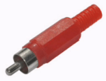
(tulip connector)- it is often found in household equipment, but can be found on some budget sound cards or monitors. Typically two connectors are used (left and right channels). In professional recording studios, tulips are used mostly as S/PDIF digital interface connectors. Sometimes they are also found as outputs for a recording device. But still, such a connector is very often found in household appliances and video equipment.
Cable wiring diagram
I will not consider the cable wiring diagram, since it is very long. But we simply cannot completely ignore such an important topic. Therefore, I am attaching graphic diagrams for wiring all the necessary connecting cables and wiring diagrams for switching various equipment in a home recording studio. Click on the image to enlarge.
You ask: “Why solder at all? Why can’t you buy ready-made connecting cables?” Yes, you can buy ready-made ones. But the problem is that not all cables are easy to find. And ready-soldered ones will cost you more than buying a separate cable, plugs and further wiring. Another advantage is that you can buy a cable of exactly the required length.
But there are also disadvantages here. The fact is that not everyone knows how to solder well. In this case, there is only one best option - to buy the necessary cable and plugs separately. And then give it all to a professional who will solder everything together efficiently. This is beneficial in every way.
Now I want to give you a number of tips on switching in a home recording studio. You should remember and follow them as much as possible. These are the recommendations:
- Use only high quality cables and connectors. Don't skimp on this. Of course, buying a cable that costs several tens of dollars per meter for less budget equipment will be pointless. But buying fake and low-quality products for a couple of rubles per meter from unknown manufacturers is also not an option. I trust manufacturers such as Klotz And Proel.
- Use the same cables to connect the same components. For example, when connecting monitors to an audio interface, each of them must be connected to the interface with the same cable. Moreover, both in terms of length and wiring, as well as by the manufacturer’s company and even the model itself.
- Choose a balanced connection. This connection produces much less noise that occurs from various interferences and allows the use of longer cables.
- Prefer connections using XLR connectors whenever possible. They have better characteristics compared to others. But if you don’t have this option, for example, when the outputs of the audio interface are jack, and the input is jack and xlr, then use a jack to jack cable.
- If you decide to solder the cables yourself, be very careful not to mix up the signal wires. Otherwise, such a thing as antiphase may occur, and when recording a stereo signal, in this case, no sound will be heard at all. And during playback, the sound will be mutually suppressed, that is, one channel will eat up the other. Therefore, if you decide to solder the cable yourself, then follow the diagrams included in this article.
This concludes our discussion of the topic. Now you know what the wiring should be like in a home recording studio. You already know what type of cable is best to use, what types of connectors there are and cable wiring diagrams. Also at the end I gave you some useful tips for connecting cables in the studio. Try to be sure to follow them.