Align the lines with a square. Aligning elements on a regular form III Line in Word using drawing
25.01.2017 28.01.2018
Good afternoon, dear visitors of the Pixelbox website!
A horizon obstruction is a photographic flaw in which the horizon line is not straight, but at an angle. The collapse of the horizon is used as an artistic device to add tragedy, movement and dynamics to a painting or photograph. If the blockage of the horizon happened by accident and does not carry any message, then it is worth correcting the defect.
A blocked horizon can happen to both novice photographers and professionals, there’s nothing wrong with that, Horizon blockage can be easily corrected in the program. Let's find out how to straighten the horizon in Photoshop. I'll show you two ways to do this - easy and more complex.
In this lesson you will learn:
- Two ways to level the horizon in Photoshop
- How to remove excess from a photo after straightening
How to level the horizon in Photoshop (1 method)
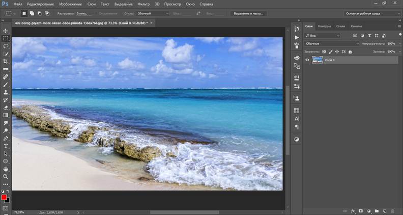
Opening a photo with a littered horizon in Photoshop (Ctrl + O).
Go to the menu Filter-Lens Correction:

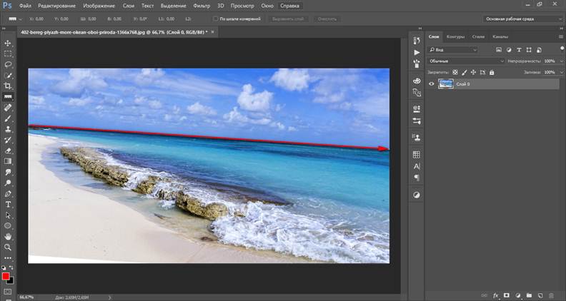
The following window will open, in which we select the second tool from the top, Straightening:

Using the mouse, draw a line in contact with the horizon. In the picture below the line is marked in red:

When the line is ready, release the mouse button. Voila!
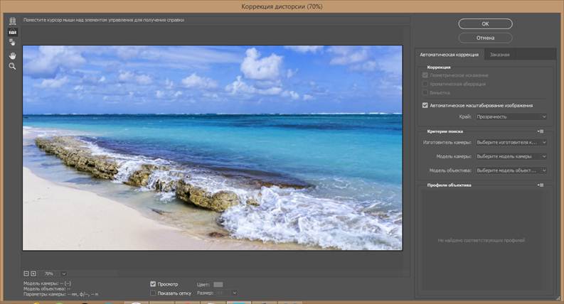
The littered horizon was straightened out in a few mouse clicks!
How to level the horizon in Photoshop (method 2)
The second method is more labor-intensive, but still has the right to life.
Activate the tool Ruler Tool I.

Draw a line again, touching the horizon present in the photo:
And press the button "Align Layer":

Result:

As you can see, unlike the first method, empty areas appeared on the edges of the photo. They need to be either trimmed or finished. If you leave it this way, after saving, the areas indicated in the document as a “checkerboard” in the image will be solid white.
Cropping the excess part of the image after leveling the horizon
To crop empty areas, activate the tool Frame (Crop Tool), hotkey for calling the tool – C.

By pulling the arrows inside the image, remove the empty areas and click the “check mark” to confirm the actions:
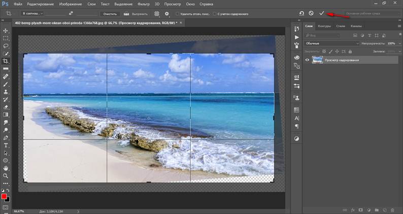
Result:

Draw empty areas using the Stamp tool
If you do not want to change the image size, which happens when cropping, you can use the tool Stamp Tool. Tool hotkey – S.

Press and hold the key Alt on the keyboard and take a sample from the photo, transfer this sample to an empty area, click the mouse button, as if attaching the area to a new location. We go through all the empty areas, if necessary, change the brush size to top panel instrument settings
We take samples frequently and make sure there are no repetitions. The final result after working with the tool Stamp:

So you have learned how to easily and simply, in 5 minutes, level the horizon and get a high-quality photograph. Make your photos even more attractive and don’t worry if they don’t turn out well on the first shot.
The main purpose of alignment lines is to help neatly arrange controls and make it easier to re-edit forms. They can also be used to visually divide a form into meaningful parts that are understandable to the form designer.
Alignment lines are a property of the panel, i.e. Each panel, and even each page of a panel, can have its own set of edge and alignment lines.
The mouse cursor above the alignment lines does not appear immediately, but with a certain delay (0.5 sec). This time interval allows, for example, to start group selection of controls from an area located outside the edge lines. Otherwise, instead of starting a selection, the edge line would shift. The sensitivity zone of the mouse cursor coincides with the capture zone (see below).
All of the following is true only for panels with the “use visible area” property set.
Adding and deleting
Each panel page can contain an unlimited number of alignment lines. There are two ways to add a new line:
- using the "Add new line" command of the context menu that appears when you click the right mouse button
- by dragging the existing alignment line, incl. and edge, with the "Ctrl" key pressed
- drag it to another alignment line, as a result of which they will merge into one
- use the "Delete alignment line" command of the context menu that appears when you right-click over the desired line
Alignment line priority
Alignment lines, both visible and invisible, take precedence over the grid. For example, you can turn off the grid, put the alignment line in an exact position, and turn on the grid. Then editable controls will be aligned to the grid only if they fail to "stick" to the alignment line.
Visible lines take precedence over invisible lines.
TOparadise alignment lines
Edge alignment lines create a visual gap between the edge of the form and the controls placed on it, preventing them from extending beyond the established boundaries. The purpose of the gap is to make the form easier to perceive by preventing controls from merging with the boundaries of the form.
Edge alignment lines are involved in defining scrollbar ranges for panels that do not have the "use visible area only" property set. Those. if there is an edge line, the panel will not scroll to the edge of the last control, but will add to it the gap formed by the alignment line.
It would seem, why might four methods be needed? After all, almost every person uses one method to which he is accustomed. For example, I pressed Shift and the dash key several times, and so I got a horizontal line.
But what if this results in a dotted line, but you need a solid one?
- Most likely, the Shift key on the keyboard is faulty. Other methods will come to the rescue here.
Perhaps the most common way to make a line in Word is to use a couple of keys on the keyboard.
I Thin, thick, double, dotted line using keyboard
Below is a picture of a keyboard with an English layout, but without a Russian layout, but this does not matter, because we are only interested in three keys: Shift, dash and Enter.

Rice. 1. Three keys on the keyboard: Shift, dash and Enter for a continuous horizontal line in Word
With these three keys you can draw a continuous horizontal line in Word: dotted or solid, thin or thick, long or short.
1) When you press the “-” (dash) key several times in the Word editor, you get a dotted line of any length.
To do thin a long line across the entire width of the page:
- We find the “dash” key on the keyboard (to the right of the “zero” key, in the green frame in Fig. 1).
- From a new (!) line in Word, press this key several times: -
- And then press the “Enter” () key. A few printed dashes will suddenly turn into a continuous horizontal thin line across the entire width of the page.
2) When you simultaneously press Shift and “-” (dash), NOT a dash is printed, but an underscore _________. This way you can make a continuous line of arbitrary length anywhere in the document.

Rice. 2. Thin and thick horizontal line in Word
Now let's print fat horizontal line across the entire width of the page:
- Again we find the same “dash” key, as well as the Shift key (on the left or on the right, as you like). Press Shift, hold and don't let go.
- And now, from a new (!) line, click on the dash several times (for example, 3-4 times) (while not releasing Shift): ___. Release Shift.
- Now press the Enter key. You will see a thick horizontal solid line.
Horizontal thin, thick, dotted and double line in Word using keyboard
II Line in Word using a table
A horizontal line can be obtained by using a table of one cell (1x1), in which only the top or bottom border is colored (will be visible), and the other three sides of the table have uncolored borders (they will be invisible).
Place the cursor in the place where the line should be. In the top menu of Word, click:
- Insert (1 in Fig. 3),
- Table (2 in Fig. 3),
- One cell (3 in Fig. 3).

Rice. 3. How to insert a 1x1 table (from one cell) in Word
The result will be a table of one large cell (1x1):
All that remains is to remove the borders from three sides in the 1x1 table. For this
- go to the “Home” tab (1 in Fig. 4),
- then next to “Font” we find “Paragraph” and borders (2 in Fig. 4),
- remove all borders by clicking “No border” (3 in Fig. 4),
- select “Upper border” or “Lower border” (4 in Fig. 4).

Rice. 4. How to remove border selection from a Word table (make borders invisible)
I show this clearly in the video (at the end of the article).
By the way, in Fig. 3 it is clear that there is an easier way. You can place the cursor at the beginning of the line in Word and click “Horizontal Line” (5 in Fig. 4):
III Line in Word using drawing
Insert (1 in Fig. 5) - Shapes (2 in Fig. 5) - this is another way to get a horizontal line in Word.
To keep the line strictly horizontal, hold down the Shift key and draw the line at the same time.

Rice. 5. How to draw a line in Word
IV Line in Word using the on-screen keyboard
For Windows 10, you can also find the on-screen keyboard by typing “on-screen keyboard” into the Search bar.

Rice. 6. On-screen keyboard
We will create a horizontal line in the same way as in the first option with a regular keyboard. You will need three buttons on the on-screen keyboard: dash, Shift and Enter.
1 Dash and Enter
From a new line in Word, click on the dash (1 in Fig. 6) several times and press Enter. You will get a thin horizontal line.
2 Shift, dash and Enter
From a new line in Word, first click Shift (2 in Fig. 6), then Dash (1 in Fig. 6). You will get an underline. We will repeat this 2 more times, and then press Enter. As a result, we will see a thick horizontal line.

Two-dimensional parity check.
In the figure, a data block consists of 14 characters, each of which has a parity bit on the left, and at the end of the block there is a parity character for the entire block. Bit 1 of the block check character checks the first bits of all characters for parity, etc. Any bit in this block is subject to parity checks, one in the horizontal direction and one in the vertical. The transmitter adds a longitudinal check character at the end of the block and transmits the data onto the line. The receiver generates its own SPB based on the received data, and then compares the calculated and received ones. If a block of data has only one bit in error, it can be accurately detected because the corresponding horizontal and vertical bits will not match. If there are two distorted bits, then the SPB value will coincide with the correct one. However, the results of the longitudinal check will not converge, and an error will be detected in the data block, but it cannot be found. The same will happen vertically if an error occurs in two characters at the same position, but a cross-sectional check will detect the error.

Horizontal and vertical checking increase the overall likelihood of error detection.
The figure shows some possible error options. Single character error 2 will be detected during both horizontal and vertical checks; double error in character 8 will be detected by vertical checking, and double character errors b and 7 will not be detected. In general, in any case where the four corrupted bits are located at the corners of the rectangle, the error will not be detected.
0 – the error is detected by longitudinal and transverse checks.
- erroneous bits are not detected.
- the error is detected only by longitudinal verification
Using mathematical analysis methods, it is possible to calculate the optimal block length that provides the maximum throughput of a particular line at a given level of undetected error.
X-ray parity checking is easy to implement in either hardware or software, but is currently usually implemented in hardware. The block check character is formed using the EXCLUSIVE OR operation on all preceding characters; Depending on the initial state (all ones or all zeros) of the memory cell allocated for the check symbol, a check for even or odd parity can be implemented. The rules for obtaining a block check character are illustrated in Figure 25, which shows two typical message formats used in a synchronous transmission system. The transmitter generates the block check character as follows. The accumulation of the block check symbol begins with the appearance of the IZ (beginning of heading) or NT (beginning of text) symbol. The first character is not included in the overall block check, and the system XORs all other characters up to and including the first occurrence of the KB (end of block) or CT (end of text) character. The resulting block check character is transmitted after the KB or CT character. The receiver scans the data until it first detects a NC or NT character. After receiving this initial symbol, the receiver begins to accumulate its own block check symbol by XORing all symbols following the NC or HT symbol up to and including the first occurrence of the KB or CT symbol. By this time the receiver has completed generating its check symbol, the next symbol received from the line is the block check symbol generated by the transmitter. If these two characters match, then a conclusion is given about the correct reception of the data block. If they do not match, then the block is considered malformed. (Note that the parity bit in the block check character applies only to that character).

Fig. 25 Formation of St. Petersburg
BLS symbols are inserted into the data stream after the block check symbol has accumulated. In some systems, SIN symbols are used as filler symbols when it is impossible to issue information symbols on the line at a pace sufficient to maintain symbol-by-symbol synchronization. Inserted SIN characters do not participate in data block verification; in practice, in most systems, the INS symbols are removed from the data stream and are not delivered to the recipient.
Cyclic check

Characteristics of various error detection methods
On regular forms, the location of elements is drawn entirely manually. To facilitate this process, the platform offers several mechanisms:
- element alignment- provides automatic centering, or “pressing” controls to each other’s guidelines, or aligning the sizes of controls:
- net- through the Options you can configure the display of the grid for precise manual alignment of elements:
The correct answer is the second one. This is a panel for aligning and unifying the sizes of elements.
Question 10.79 of exam 1C: Platform Professional.
- Nothing will change
- The element "Inscription1" will be shifted horizontally and its right border will be aligned with the right border of the element "Inscription2"
- The element "Inscription2" will be shifted horizontally and its right border will be aligned with the right border of the element "Inscription1"
- Both elements will move to the right edge alignment line of the form
The correct answer is the second one. The labels will be aligned to the right.
Question 10.82 of exam 1C: Platform Professional. What happens when you click the command bar button marked in the picture?
- All inscriptions will be the same size horizontally
- Nothing will change
- The labels will shift. The vertical axis of symmetry of each control element will coincide with the vertical axis of symmetry of the form, i.e. centering each control horizontally
- The labels will shift horizontally. The controls will not move relative to each other within the group, i.e. centering, as it were, one element as a whole
- The labels will shift vertically. The controls will not move relative to each other within the group, i.e. centering, as it were, one element as a whole
The correct answer is fourth. All selected controls will be centered around their common center line.
Question 10.83 of exam 1C: Platform Professional. What happens when you click the command bar button marked in the picture?
- All inscriptions will be the same size vertically. The "Inscription1" control element will be taken as a sample.
- Nothing will change
- All inscriptions will be the same size vertically. The "Inscription3" control element will be taken as a sample.
- Each label will be centered vertically
- There will be an even distribution of inscriptions in the vertical direction. The controls "Inscription1" and "Inscription3" will remain in place, and the element "Inscription2" will be moved in the desired direction. When moving an element, the snap to the layout grid is not taken into account
- There will be an even distribution of inscriptions in the vertical direction. The controls "Inscription1" and "Inscription3" will remain in place, and the element "Inscription2" will be moved in the desired direction. When you move an element, it will snap to the marking grid if the mode for its use is set
The correct answer is the first one. The height of the elements will be standardized
Question 10.86 of exam 1C: Platform Professional. What happens if you click the command bar button canceled in the picture?
- All inscriptions will be the same size vertically and horizontally. The "Inscription1" control element will be taken as a sample.
- All inscriptions will be the same size vertically and horizontally. The "Inscription3" control element will be taken as a sample.
- Nothing will change
- Labels will be automatically aligned
- All labels will have a transparent background.
The correct answer is number four, the button itself is called "Align automatically"
Question 10.90 of exam 1C: Platform Professional. Disable alignment mode using alignment lines in a previously created form:
- It is forbidden
- Can. To do this, in the form properties palette, you need to disable the "Use alignment lines" property.
- Can. To do this, by selecting the main menu item "Tools-Options", on the "Form" tab, you need to disable the "Use alignment lines" property
- Can. To do this, in the form properties palette you need to disable the "Use alignment lines" property or, by selecting the "Tools-Options" main menu item, on the "Form" tab, disable the "Use alignment lines" property
The correct answer is the second one. Alignment lines (marked with an arrow) are disabled by the corresponding form property:
Question 10.92 of exam 1C: Platform Professional. When aligning form elements, a layout grid may be shown:
- Continuous lines
- Checkerboard dots
- Points located at the intersection of marking lines
- Answers 1 and 2 are correct
- Answers 2 and 3 are correct
- Answers 1, 2 and 3 are correct
The correct answer is number five. The location of the points is controlled by the Checkerboard option in the System Parameters (see screenshot in the post).
Question 10.95 of exam 1C: Platform Professional.
- A special alignment marker that shows the offset of controls. The selected control element is offered to be moved to the left
- A special alignment marker that shows the offset of controls. The selected control element is offered to be moved down
- A special alignment marker showing the overlay of controls. The selected control element is offered to be moved to the left
- A special alignment marker showing the overlay of controls. The selected control element is offered to be moved down
The correct answer is the first one. The bottom margin is shifted to the right relative to the top, so it is proposed to move it to the left.
Question 10.96 of exam 1C: Platform Professional. Can I use alignment lines to resize and move form controls?
- It is forbidden
- Yes, if the controls are attached to these lines
- It is possible if the controls are attached to these lines, but only move them
- It is possible if the controls are attached to these lines, but only resize
- You can, always
The correct answer is the second one. Elements attached to the same guyline can be moved together.
Question 10.97 of exam 1C: Platform Professional. In the figure the red circle marks:
- A special alignment marker that shows the offset of controls. The selected control element is offered to be moved to the left and up
- A special alignment marker that shows the offset of controls. The selected control element can be moved to the right and down
- A special alignment marker showing the overlay of controls. The selected control element is offered to be moved to the left and up
- A special alignment marker showing the overlay of controls. The selected control element can be moved to the right and down
The correct answer is fourth. Where the arrows point, you need to move there.
Question 10.98 of exam 1C: Platform Professional. In the figure the red circle marks:
Question 10.110 of exam 1C: Platform Professional. How can I use the command bar button shown in the figure to align all three labels to the right?
- First, select the “Inscription1” control by clicking on it with the left mouse button and simultaneously pressing the key. Then press the indicated button
- Just click on the indicated button
- Using this button you cannot align the labels, since they belong to different panels
Question 10.115 of exam 1C: Platform Professional. To display a layout grid in an existing form, it is enough:
- In the form properties palette, set the "Use Grid" property
- By selecting the main menu item "Tools-Options", on the "Form" tab, set the "Use Grid" flag
- By selecting the main menu item "Tools-Options", on the "Form" tab, set the "Display grid" flag
- By selecting the main menu item "Tools-Options", on the "Form" tab, set the "Display Grid" flag, and then in the form properties palette set the "Use Grid" property
- By selecting the main menu item "Tools-Options", on the "Form" tab, set the "Display Grid" and "Use Grid" flags
The correct answer is fourth; for the form you can also specify the option to display or not.